 |
Place the timing chain cover on wooden blocks.
OIL PUMP > INSTALLATION |
| 1. REPLACE TIMING CHAIN COVER OIL SEAL |
|
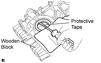
Place the timing chain cover on wooden blocks.
Using a screwdriver with its tip taped, pry out the oil seal.
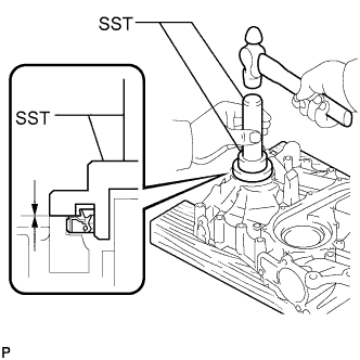 |
Using SST and a hammer, tap in a new oil seal until its surface is flush with the timing chain cover edge.
Apply a light coat of MP grease to a new oil seal lip.
| 2. INSTALL ENGINE WATER PUMP ASSEMBLY |
Install a new gasket and the engine water pump with the 8 bolts.
| 3. INSTALL TIMING CHAIN COVER SUB-ASSEMBLY |
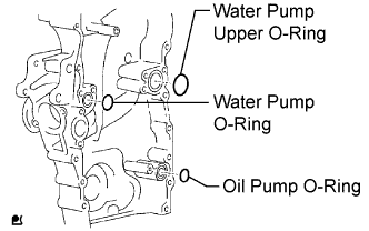 |
Install 3 new O-rings to the timing chain cover as shown in the illustration.
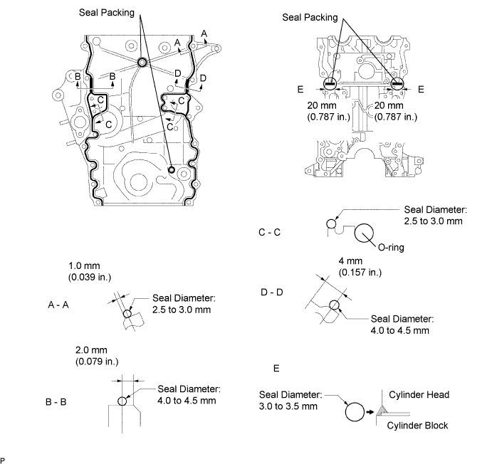
Apply seal packing in a continuous line as shown in the illustration.
| Position | Specified Condition |
| A - A, C - C | 2.5 to 3.0 mm (0.098 to 0.118 in.) |
| B - B, D - D | 4.0 to 4.5 mm (0.157 to 0.177 in.) |
| E | 3.0 to 3.5 mm (0.118 to 0.138 in.) |
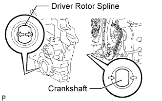 |
Align the oil pump drive rotor spline and crankshaft as shown in the illustration. Install the drive rotor and chain cover to the crankshaft.
Temporarily install the timing chain cover with the 19 bolts and 2 nuts.
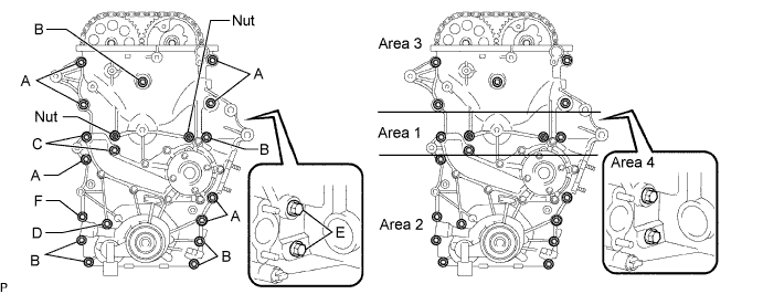
Excluding the bolts labeled A and C, tighten the bolts and nuts in this order: Area 1, Area 2 and Area 3.
| Item | Length | Thread Diameter |
| Bolt A | 75 mm (2.95 in.) | 10 mm (0.394 in.) |
| Bolt B | 75 mm (2.95 in.) | 8 mm (0.315 in.) |
| Bolt C | 90 mm (3.54 in.) | 8 mm (0.315 in.) |
| Bolt D | 95 mm (3.74 in.) | 8 mm (0.315 in.) |
| Bolt E | 35 mm (1.38 in.) | 8 mm (0.315 in.) |
| Bolt F | 75 mm (2.95 in.) | 10 mm (0.394 in.) |
Excluding the bolts labeled A, E and F, tighten the bolts and nuts in this order: Area 1, Area 3, Area 2.
Tighten the bolts labeled A in this order: Area 2 and Area 3.
Tighten the bolt labeled F.
Tighten the bolts labeled E in Area 4.
Apply adhesive to the timing gear case plug.
Using a 10 mm socket hexagon wrench, install the timing gear case plug.
| 4. INSTALL V-RIBBED BELT TENSIONER ASSEMBLY |
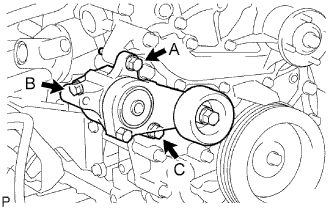 |
Temporarily install the belt tensioner with the 3 bolts.
Install the tensioner with the 3 bolts.
| 5. INSTALL CRANKSHAFT POSITION SENSOR |
Apply a light coat of engine oil to the O-ring of the sensor.
Install the sensor with the bolt.
Install the connector to the connector bracket.
Attach the harness clamp.
Connect the sensor connector.
| 6. INSTALL OIL PAN SUB-ASSEMBLY |
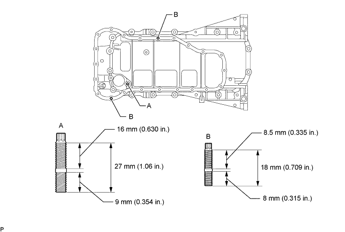
Install the stud bolt.
Using E5 and E7 "TORX" socket wrenches, install the stud bolts.
 |
Install a new tight plug.
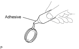
Apply adhesive around a new tight plug.
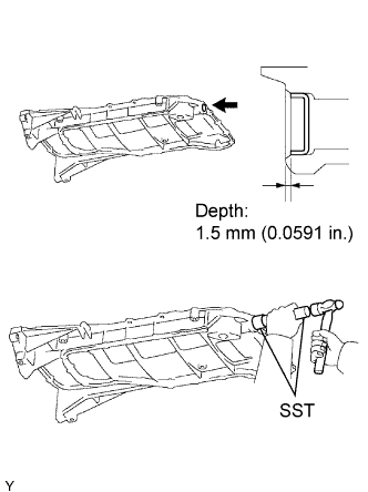 |
Using SST and a hammer, tap in the tight plug as shown in the illustration.
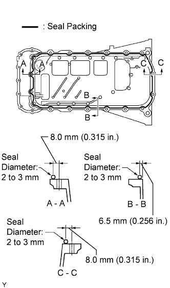 |
Apply seal packing in a continuous line to the places shown in the illustration.
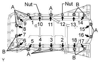 |
Temporarily install the oil pan with the 16 bolts and 2 nuts.
Uniformly tighten the 16 bolts and 2 nuts in the sequence shown in the illustration.
| 7. INSTALL OIL STRAINER SUB-ASSEMBLY |
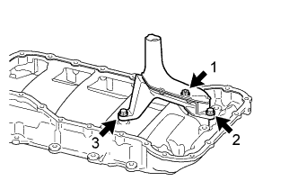 |
Install a new gasket and the oil strainer sub-assembly with the 2 bolts and nut in the sequence shown in the illustration.
| 8. INSTALL NO. 2 OIL PAN SUB-ASSEMBLY |
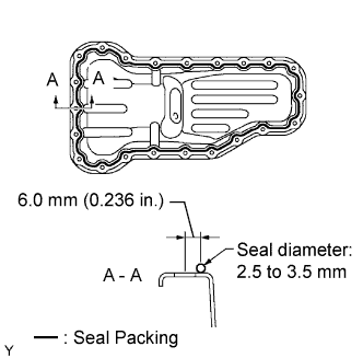 |
Apply seal packing in a continuous line to the places shown in the illustration.
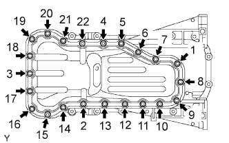 |
Temporarily install the oil pan with the 20 bolts and 2 nuts.
Uniformly tighten the 20 bolts and 2 nuts in the sequence shown in the illustration.
Install a new gasket and the drain plug.
| 9. INSTALL CRANKSHAFT PULLEY |
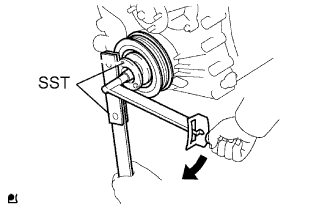 |
Align the pulley set key with the key groove of the pulley, and slide on the pulley.
Using SST, install the crankshaft pulley bolt.
| 10. INSTALL CAMSHAFT POSITION SENSOR |
Apply a light coat of engine oil to the O-ring of the sensor.
Install the sensor with the bolt.
Connect the sensor connector.
| 11. INSTALL CYLINDER HEAD COVER SUB-ASSEMBLY |
Install the 2 gaskets to the head cover.
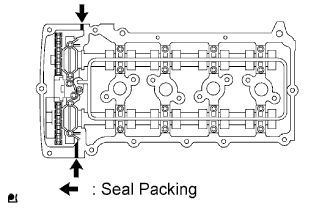 |
Apply seal packing to the places shown in the illustration.
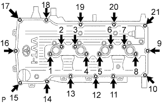 |
Temporarily install the cover with the 19 bolts and 2 nuts.
Uniformly tighten the 19 bolts and 2 nuts in the sequence shown in the illustration.
In numerical order, confirm that the bolts labeled 1 to 8 are tighten to the torque specification. Tighten the bolts as necessary.
| 12. INSTALL OIL FILLER CAP SUB-ASSEMBLY |
| 13. INSTALL NO. 1 WATER BY-PASS PIPE |
Install the end plate with the bolt.
Connect the No. 1 water by-pass pipe from the rear end plate with the bolt.
| 14. INSTALL NO. 1 IDLER PULLEY SUB-ASSEMBLY |
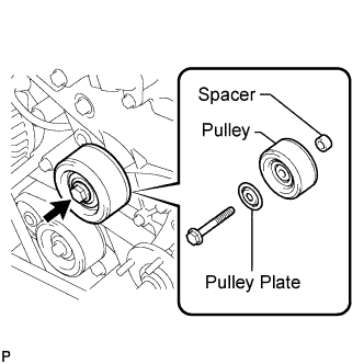 |
Install the spacer and pulley with the bolt.
| 15. INSTALL THERMOSTAT |
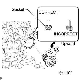 |
Install a new gasket to the thermostat.
Insert the thermostat with the jiggle valve upward.
| 16. INSTALL WATER INLET |
Install a new gasket and the water inlet with the 2 nuts and bolt.
Connect the power steering pump connector.
| 17. INSTALL NO. 1 COMPRESSOR MOUNTING BRACKET |
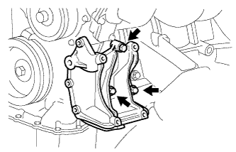 |
Temporarily install the No. 1 compressor mounting bracket with the 3 bolts.
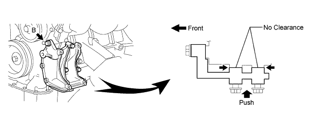
Push the No. 1 compressor mounting bracket toward the cylinder block as shown in the illustration and tighten bolt B.
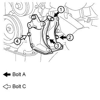 |
Uniformly tighten the 4 bolts in the order shown in the illustration.
| 18. INSTALL GENERATOR ASSEMBLY |
Install the generator with the 2 bolts.
Connect the generator connector.
Install the generator wire with the bolt and nut.
Attach the terminal cap.
| 19. INSTALL INTAKE MANIFOLD |
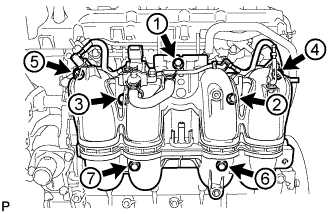 |
Install a new gasket and the intake manifold with the 5 bolts and 2 nuts in the order shown in the illustration.
Connect the purge line hose and purge VSV connector.
Connect the fuel hose and vacuum hose.
| 20. INSTALL FUEL INJECTOR ASSEMBLY |
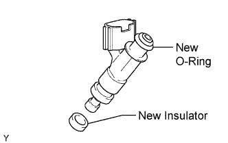 |
Install a new insulator to the fuel injector.
Apply a light coat of grease or gasoline to a new O-ring and install it to the fuel injector.
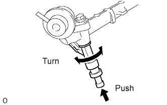 |
Apply a light coat of grease or gasoline on the place where the delivery pipe touches the O-ring.
To install the fuel injector into the fuel delivery pipe, push the fuel injector while twisting it back and forth.
Position the fuel injector connector so that it faces downward.
| 21. INSTALL FUEL DELIVERY PIPE SUB-ASSEMBLY |
Apply a light coat of gasoline or spindle oil to new O-rings, and then install one to each spacer.
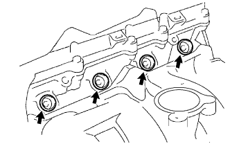 |
Install the 4 spacers to the cylinder head.
Install 4 new injector vibration insulators to the cylinder head.
Install the 2 No. 1 delivery pipe spacers to the cylinder head.
Install the fuel delivery pipe together with the 4 fuel injectors with the 2 bolts.
Connect the 4 injector connectors.
Connect the 4 clamps and wire harness to the delivery pipe.
Connect the vacuum hose.
| 22. INSTALL THROTTLE BODY WITH MOTOR ASSEMBLY |
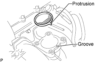 |
Install a new gasket on the intake manifold.
Install the throttle body with motor with the 4 bolts.
Connect the 2 water by-pass hoses to the throttle body with motor.
Connect the throttle position sensor and control motor connector.
| 23. INSTALL PCV PIPE |
Install the PCV pipe with the bolt.
| 24. INSTALL SPARK PLUG |
Using a 16 mm plug wrench, install the 4 spark plugs.
| 25. INSTALL IGNITION COIL ASSEMBLY |
Install the 4 ignition coils with the 4 bolts.
Connect the ignition coil connector.
| 26. REMOVE ENGINE FROM ENGINE STAND |
Attach an engine sling device and hang the engine with a chain block.
Lift the engine and remove it from the engine stand.
Place the engine onto a work bench.
| 27. INSTALL ENGINE ASSEMBLY |