 |
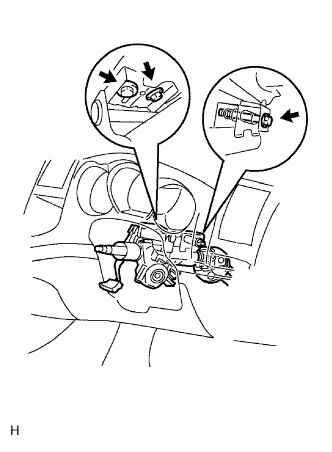
Install the steering column with the 3 bolts.
- Torque:
- 21 N*m{ 214 kgf*cm , 15 ft.*lbf }
STEERING COLUMN ASSEMBLY > INSTALLATION |
| 1. INSTALL STEERING COLUMN ASSEMBLY |
|
Install the steering column with the 3 bolts.
| 2. INSTALL STEERING COLUMN HOLE COVER SUB-ASSEMBLY |
Install the cover with the 3 bolts.
| 3. CONNECT CONNECTOR |
Connect the connectors and attach the wire harness clamps to the steering column.
| 4. INSTALL STEERING SLIDING YOKE |
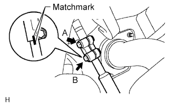 |
Align the matchmarks on the steering yoke and steering intermediate shaft.
Install the bolt labeled B.
Tighten the bolt labeled A.
| 5. INSTALL LOWER INSTRUMENT PANEL SUB-ASSEMBLY |
for Automatic Air Conditioning System:
Connect the room temperature sensor.
Attach the 2 guides to install the lower instrument panel.
Connect the connectors and attach the clamps.
Connect the hood lock control cable, fuel lid lock control cable and DLC3.
Install the 2 bolts <C>, nut <D> and 3 screws <E>.
Install the 2 clips <B>.
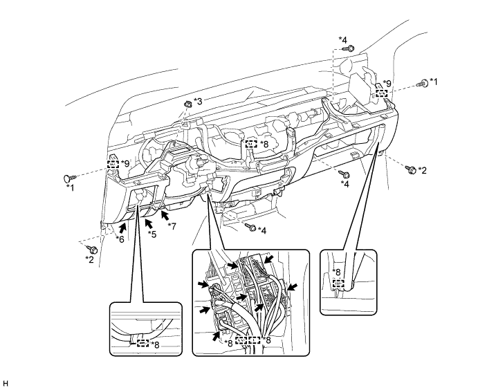
| *1 | Clip <B> | *2 | Bolt <C> |
| *3 | Nut <D> | *4 | Screw <E> |
| *5 | Hood Lock Control Cable | *6 | Fuel Lid Lock Control Cable |
| *7 | DLC3 | *8 | Clamp |
| *9 | Guide | - | - |
| 6. INSTALL UPPER INSTRUMENT PANEL SUB-ASSEMBLY |
Attach the 5 guides and 8 claws to install the upper instrument panel.
Install the 2 bolts <A> and 2 screws <B>.
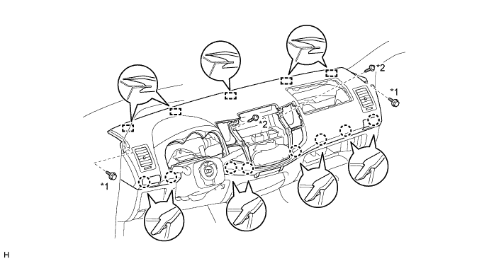
| *1 | Bolt <A> | *2 | Screw <B> |
| 7. INSTALL HEADLIGHT DIMMER SWITCH ASSEMBLY |
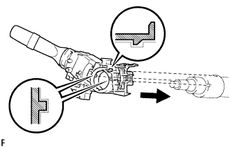 |
Install the headlight dimmer switch assembly to the steering column, making sure that the stopper protrusions and cutout parts align.
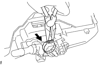 |
Using needle-nose pliers, install the band clamp as shown in the illustration.
Connect the connector.
| 8. INSTALL WIPER AND WASHER SWITCH ASSEMBLY |
Attach the claw to install the windshield wiper switch.
Connect the connectors.
| 9. INSTALL SPIRAL CABLE SUB-ASSEMBLY |
Check that the front wheels are facing straight ahead.
Set the turn signal switch to the neutral position.
Install the spiral cable.
Connect the connectors to the spiral cable.
| 10. INSTALL INSTRUMENT NO. 1 CLUSTER FINISH PANEL |
Attach the 2 claws and 3 guides to install the No. 1 instrument cluster finish panel.
Install the clip <C>.
| 11. INSTALL STEERING COLUMN UPPER COVER |
| 12. INSTALL STEERING COLUMN LOWER COVER |
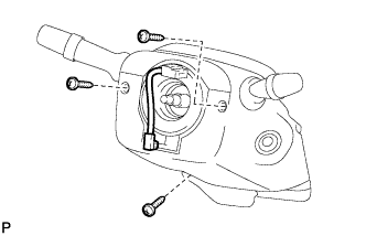 |
Install the lower cover with the 3 screws.
| 13. INSTALL STEERING WHEEL ASSEMBLY |
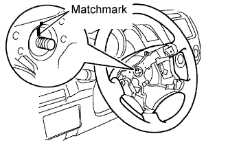 |
Align the matchmarks on the steering wheel and main shaft.
Install the steering set nut.
| 14. INSTALL STEERING PAD ASSEMBLY |
With the steering pad installed on the vehicle, perform a visual check. If there are any defects as mentioned below, replace the steering pad with a new one:
Cuts, minute cracks or marked discoloration on the steering pad top surface or in the grooved portion.
Make sure that the horn sounds.
If the horn does not sound, inspect the horn system.
| 15. INSTALL STEERING PAD SWITCH ASSEMBLY (w/ Multi-information Display) |
Attach the 4 pins to install the steering pad switch.
Install the 2 screws.
Connect the connectors and attach the 2 clamps.
| 16. INSTALL STEERING PAD SWITCH LH (w/o Multi-information Display) |
| 17. PLACE FRONT WHEELS FACING STRAIGHT AHEAD |
| 18. CONNECT CABLE TO NEGATIVE BATTERY TERMINAL |
| 19. PERFORM INITIALIZATION |
Perform initialization (Click here).