Home › ENGINE ยท 1KD-FTV › COOLING › WATER PUMP (w/o Glow Plug Controller)

WATER PUMP (w/o Glow Plug Controller) > INSTALLATION

for Preparation Click here


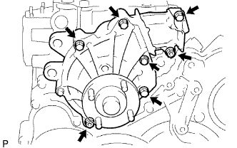
1. INSTALL WATER PUMP ASSEMBLY


    A225339
  1. Install a new gasket and the water pump with the 5 bolts and 2 nuts.

    Torque:
    13 N*m{ 133 kgf*cm , 10 ft.*lbf }


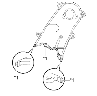
2. INSTALL NO. 2 TIMING BELT COVER


    A060279E02
  1. Apply seal packing (FIPG) to the specified areas shown in the illustration.

    Seal packing:
    Toyota Genuine Seal Packing Black, Three Bond 1207B or equivalent

    Text in Illustration 
    *1
    Seal Packing

    NOTICE:
    After applying seal packing, install the No. 2 timing belt cover within 3 minutes and tighten the bolts and nut within 15 minutes.

  1. Clean the bolts and their holes.

  1. Apply adhesive to 2 or 3 threads at the end of each of the 4 bolts.

    Adhesive:
    Toyota Genuine Adhesive 1324, Three Bond 1324 or equivalent

  1. Install the No. 2 timing belt cover with the 4 bolts and nut.

    Torque:
    10 N*m{ 102 kgf*cm , 7 ft.*lbf }


3. INSTALL CAMSHAFT TIMING PULLEY
  1. Install the camshaft timing pulley.

  1. Install the bolt of the camshaft timing pulley while holding the camshaft with a wrench.

    Torque:
    98 N*m{ 1000 kgf*cm , 72 ft.*lbf }


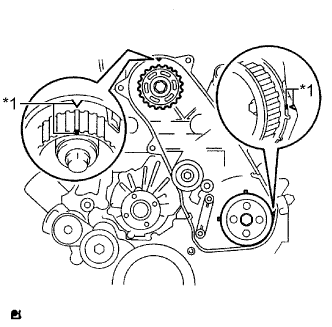
4. INSTALL TIMING BELT


    A070691E05
  1. Check that the timing marks are aligned as shown in the illustration.
    Text in Illustration 
    *1
    Timing Mark

    NOTICE:
    1. Make sure that the engine is cold.
    2. When turning the crankshaft, the valve heads will hit against the piston. Do not turn the crankshaft more than necessary.

    HINT:
    If reusing the timing belt, align the points marked during removal, and install the belt with the arrow pointing in the direction of crankshaft revolution.

  1. Install the timing belt to the pump drive shaft pulley, camshaft timing pulley and No. 1 timing belt idler in sequence.


    A070548E01
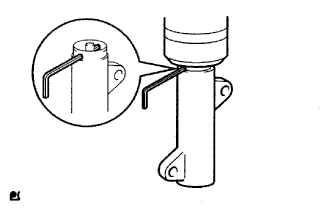
  1. Place the tensioner upright. Then set a press on the top of the tensioner.

    NOTICE:
    1. Do not scratch or deform the rod end.
    2. Press in the tensioner rod.
    3. Protect the tip of the push rod with a cloth in order to prevent damage.

  1. Using the press, slowly push in the push rod using 981 to 9800 N (100 to 999 kgf, 220 to 2203 lbf) of force.

    NOTICE:
    Do not apply a load of over 9800 N (999 kgf, 2203 lbf) to the push rod.

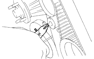
  1. Align the holes of the push rod and housing. Then pass a 1.5 mm hexagon wrench through the holes to fix the push rod in place.

  1. Temporarily install the timing belt tensioner with the 2 bolts while pushing the idler pulley toward the timing belt.

  1. Tighten the 2 bolts.

    Torque:
    13 N*m{ 133 kgf*cm , 10 ft.*lbf }

    NOTICE:
    Uniformly tighten the 2 bolts.


    A059983E01
  1. Remove the 1.5 mm hexagon wrench from the tensioner.


    A070549E05
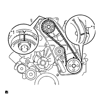
  1. Turn the crankshaft clockwise 720° and check that the timing marks are aligned as shown in the illustration.
    Text in Illustration 
    *1
    Timing Mark


5. INSTALL NO. 1 TIMING BELT IDLER SUB-ASSEMBLY


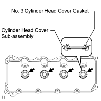
6. INSTALL CYLINDER HEAD COVER SUB-ASSEMBLY


    A272954E01
  1. Install 4 new No. 3 cylinder head cover gaskets to the cylinder head cover in the directions shown in the illustration.

    NOTICE:
    1. Do not install the No. 3 cylinder head cover gaskets at an angle.
    2. Check that there is no foreign matter at the installation location of the No. 3 cylinder head cover gaskets.

  1. Remove any old seal packing (FIPG material) from the cylinder head.


    A257065E01
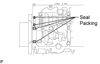
  1. Apply seal packing to the specific areas shown in the illustration.

    Seal packing:
    Toyota Genuine Seal Packing Black, Three Bond 1207B or equivalent

    NOTICE:
    1. Remove any oil from the contact surface.
    2. Install the head cover within 3 minutes after applying seal packing.
    3. Do not start the engine for at least 2 hours after installing the seal packing.

  1. Install a new cylinder head cover gasket and the cylinder head cover with the 10 bolts and 2 nuts.

    Torque:
    9.0 N*m{ 92 kgf*cm , 80 in.*lbf }

  1. Install 4 new nozzle holder seals.

  1. Connect the ventilation hose.

  1. Connect the 4 connectors and install the 3 bolts.

    Torque:
    13 N*m{ 127 kgf*cm , 9 ft.*lbf }


7. INSTALL INJECTION PIPE

NOTICE:
  1. When replacing an injector, it is necessary to replace the 4 injection pipes with new ones.
  2. Keep the joints of the injection pipes clean.

  1. Temporarily install the No. 1, No. 2 and No. 3 injection pipes with the union nuts.


    A246458E02
  1. w/ EGR Cooler:
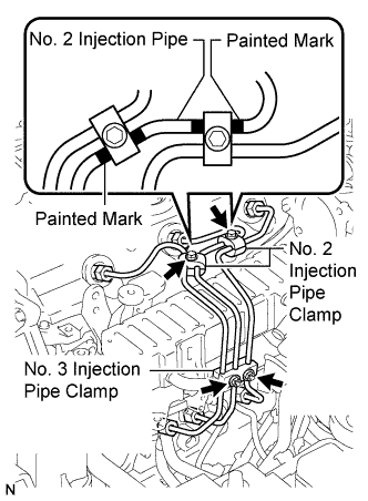
    Install the No. 2 and No. 3 injection pipe clamps with the 2 bolts and 2 nuts as shown in the illustration.
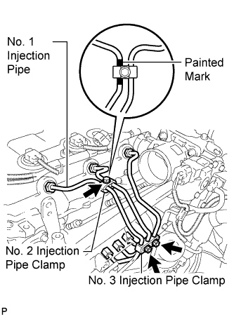
    Torque:
    5.0 N*m{ 51 kgf*cm , 44 in.*lbf }

    HINT:
    If the painted mark on the No. 2 injection pipe has disappeared, use the illustration as a reference to install the clamps.


    A231806E01
  1. w/o EGR Cooler:
    Install the No. 2 and No. 3 injection pipe clamps with the bolt and 2 nuts as shown in the illustration.

    Torque:
    5.0 N*m{ 51 kgf*cm , 44 in.*lbf }

    HINT:
    If the painted mark on the No. 1 injection pipe has disappeared, use the illustration as a reference to install the clamps.

  1. Using a 17 mm union nut wrench, tighten the injection pipe union nuts on the common rail side.

    Torque:
    35 N*m{ 357 kgf*cm , 26 ft.*lbf }

    NOTICE:
    Use the formula to calculate special torque values for situations where a union nut wrench is combined with a torque wrench (Click here).

  1. Using a 17 mm union nut wrench, tighten the injection pipe union nuts on the injector side.

    Torque:
    35 N*m{ 357 kgf*cm , 26 ft.*lbf }

    NOTICE:
    Use the formula to calculate special torque values for situations where a union nut wrench is combined with a torque wrench (Click here).


8. INSTALL NO. 1 TIMING BELT COVER
  1. Install the timing belt cover and 6 washers with the 6 bolts.

    Torque:
    6.0 N*m{ 61 kgf*cm , 53 in.*lbf }


9. INSTALL CHARGE AIR COOLER ASSEMBLY
  1. Install the CAC (Click here).


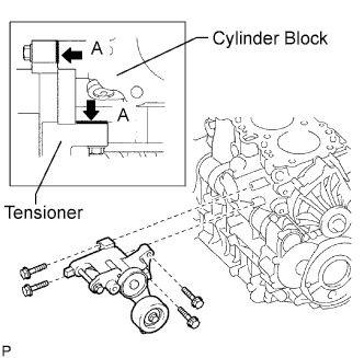
10. INSTALL V-RIBBED BELT TENSIONER ASSEMBLY


A097638E02
  1. Install the tensioner with the 4 bolts.

    Torque:
    21 N*m{ 214 kgf*cm , 15 ft.*lbf }

    HINT:
    Firmly press and hold the tensioner against the cylinder block to eliminate any gaps in the A areas shown in the illustration. Then uniformly tighten the 4 bolts.


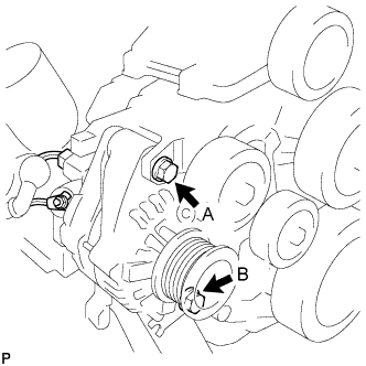
11. INSTALL GENERATOR ASSEMBLY


A111821E01
  1. Install the generator and adjusting bar with the 2 bolts.

    Torque:
    62 N*m{ 632 kgf*cm , 46 ft.*lbf } for bolt A
    25 N*m{ 255 kgf*cm , 18 ft.*lbf } for bolt B

  1. Install the generator wire with the nut.

    Torque:
    9.8 N*m{ 100 kgf*cm , 87 in.*lbf }

  1. Connect the generator connector.


12. INSTALL COOLER COMPRESSOR ASSEMBLY
  1. Install the compressor with the 4 bolts.

    Torque:
    24.5 N*m{ 250 kgf*cm , 18 ft.*lbf }


13. INSTALL FAN SHROUD
  1. Install the fan pulley to the water pump.

  1. Install the shroud together with the coupling fan between the radiator and engine component.

    NOTICE:
    Be careful not to damage the radiator core.

  1. Install the fluid coupling fan to the water pump with the 4 nuts.
    Tighten the nuts as much as possible by hand.
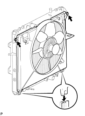


    A110385
  1. Attach the shroud's claws to the radiator.

  1. Install the shroud with the 2 bolts.

    Torque:
    5.0 N*m{ 51 kgf*cm , 44 in.*lbf }

  1. Install the drive belt .

  1. Tighten the 4 nuts of the fluid coupling fan.
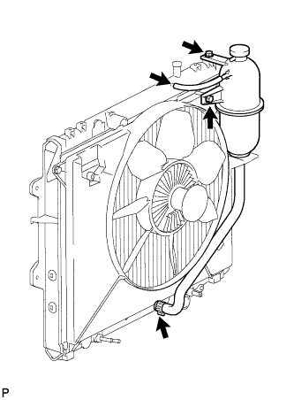
    Torque:
    23 N*m{ 235 kgf*cm , 17 ft.*lbf }


    A110386
  1. Install the radiator reservoir with the 2 bolts.

    Torque:
    5.0 N*m{ 51 kgf*cm , 44 in.*lbf }

  1. Connect the No. 1 and No. 2 water by-pass hoses to the tank upper and lower.
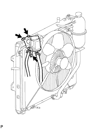


    A110387
  1. Install the oil reservoir with the 3 bolts.

    Torque:
    4.5 N*m{ 46 kgf*cm , 40 in.*lbf }


14. CONNECT RADIATOR HOSE INLET


15. ADD ENGINE COOLANT
  1. Tighten the radiator drain cock plug by hand.

  1. Tighten the cylinder block drain cock plug.
    Torque:
    8.0 N*m{ 82 kgf*cm , 71 in.*lbf }


    A098989E01
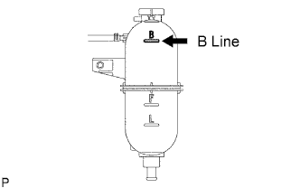
  1. Fill the radiator with TOYOTA Super Long Life Coolant (SLLC) to the reservoir tank's B line.

    Standard capacity:
    Item
    Specified Condition
    A/T
    11.1 liters (11.7 US qts, 9.8 Imp. qts)
    M/T
    9.8 liters (10.4 US qts, 8.6 Imp. qts)

    HINT:
    1. TOYOTA vehicles are filled with TOYOTA SLLC at the factory. In order to avoid damage to the engine cooling system and other technical problems, only use TOYOTA SLLC or similar high quality ethylene glycol based non-silicate, non-amine, non-nitrite, non-borate coolant with long-life hybrid organic acid technology (coolant with long-life hybrid organic acid technology consists of a combination of low phosphates and organic acids).
    1. Please contact your TOYOTA dealer for further details.

    NOTICE:
    Never use water as a substitute for engine coolant.

  1. Press the inlet and outlet radiator hoses several times by hand, and then check the level of the coolant.
    If the coolant level drops below the B line, add TOYOTA SLLC to the B line.

  1. Install the radiator reservoir cap.


    A099591E01
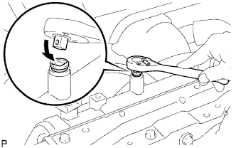
  1. Using a wrench, install the vent plug.

    Torque:
    2.0 N*m{ 20 kgf*cm , 18 in.*lbf }

  1. Bleed air from the cooling system.

    1. Warm up the engine until the thermostat opens. While the thermostat is open, circulate the coolant for several minutes.

    2. Maintain the engine speed at 2,500 to 3,000 rpm.

    3. Press the inlet and outlet radiator hoses several times by hand to bleed air.

      CAUTION:
      When pressing the radiator hoses:
      1. Wear protective gloves.
      1. Be careful as the radiator hoses are hot.
      1. Keep your hands away from the radiator fan.

    4. Stop the engine and wait until the coolant cools down to ambient temperature.
      CAUTION:
      Do not remove the radiator reservoir cap while the engine and radiator are still hot. Pressurized, hot engine coolant and steam may be released and cause serious burns.


    G036768E01
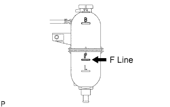
  1. After the coolant cools down, check that the coolant level is at the F line.
    If the coolant level is below the F line, add TOYOTA SLLC to the F line.


16. CONNECT CABLE TO NEGATIVE BATTERY TERMINAL


17. CHECK FOR ENGINE COOLANT LEAKS
  1. Check for coolant leaks (Click here).


18. CHECK FOR ENGINE OIL LEAKS


19. INSTALL NO. 1 ENGINE UNDER COVER

Torque:
28 N*m{ 286 kgf*cm , 21 ft.*lbf }


20. PERFORM INITIALIZATION
  1. Perform initialization (Click here).

    NOTICE:
    Certain systems need to be initialized after disconnecting and reconnecting the cable from the negative (-) battery terminal.