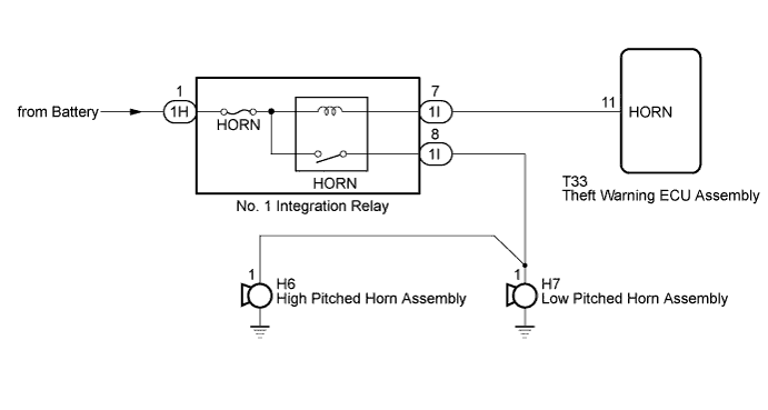
THEFT DETERRENT SYSTEM > Horn Circuit |
| 1.CHECK HORN ASSEMBLY |
Press the horn switch and check if the horns sound.
| Result | Proceed to |
| Horns sound | A |
| Horns do not sound | B |
|
| ||||
| A | |
 |
| 2.CHECK HARNESS AND CONNECTOR (THEFT WARNING ECU - NO. 1 INTEGRATION RELAY [HORN RELAY]) |
Disconnect the T33 theft warning ECU assembly connector.
Disconnect the 1I No. 1 integration relay connector.
Measure the resistance according to the value(s) in the table below.
| Tester Connection | Condition | Specified Condition |
| T33-11 (HORN) - 1I-7 | Always | Below 1 Ω |
| T33-11 (HORN) or 1I-7 - Body ground | Always | 10 kΩ or higher |
|
| ||||
| OK | ||
 | ||
| ||
