| B |  |
| GO TO DTC CHART (Click here) |
DTC P1251 Turbocharger / Supercharger Overboost Condition (Too High) |
| DTC Detection Drive Pattern | DTC Detection Condition | Trouble Area |
| Vehicle being driven | Boost pressure is higher than the threshold* for 5 seconds. (1 trip detection logic). |
|
| DTC No. | Data List |
| P1251 |
|
| 1.CHECK FOR ANY OTHER DTCS OUTPUT (RECORD STORED DTC AND FREEZE FRAME DATA) |
Connect the intelligent tester to the DLC3.
Turn the ignition switch to ON and turn the tester on.
Enter the following menus: Powertrain / Engine and ECT / DTC.
Read the DTCs.
| Result | Proceed to |
| P1251 is output | A |
| P1251 and other DTCs are output | B |
|
| ||||
| A | |
 |
| 2.CHECK AIR INTAKE SYSTEM |
Check if the hoses between the air cleaner and turbocharger, and turbocharger and intake manifold are damaged or disconnected.
| Result | Proceed to |
| Hoses or pipes are damaged or disconnected | A |
| No hoses or pipes are damaged or disconnected | B |
|
| ||||
| A | |
|
| 3.REPAIR OR REPLACE AIR INTAKE SYSTEM |
Repair or replace the malfunctioning part in the air intake system.
| NEXT | |
|
| 4.CHECK TURBOCHARGER SUB-ASSEMBLY (DC MOTOR OPERATION) |
Check the turbocharger sub-assembly (Click here).
|
| ||||
| OK | |
|
| 5.PERFORM ACTIVE TEST USING INTELLIGENT TESTER (ACTIVATE THE EGR VALVE CLOSE) |
Connect the intelligent tester to the DLC3.
Start the engine and warm it up, and make sure the A/C switch and all accessory switches are off.
Turn the ignition switch off. Wait for 30 seconds, and then restart the engine.
Turn the tester on.
Enter the following menus: Powertrain / Engine and ECT / Data List / MAF.
Read the MAF value displayed on the tester while the engine is idling.
Enter the following menus: Powertrain / Engine and ECT / Active Test / Activate the EGR Valve Close.
Read the MAF value when the EGR valve is closed using the Active Test function.
| Active Test | Result | Proceed to |
| Activate the EGR Valve Close: Off (Open) to On (Closed) | MAF value does not change | A |
| MAF value changes | B |
| EGR Valve Condition (Opening) | Measuring Condition | MAF (Reference) |
| Open (55%) |
| 3.0 to 9.0 gm/s |
| Closed (0%) | 15 to 22 gm/s |
|
| ||||
| A | |
|
| 6.CHECK ELECTRIC EGR CONTROL VALVE ASSEMBLY (CHECK VACUUM) |
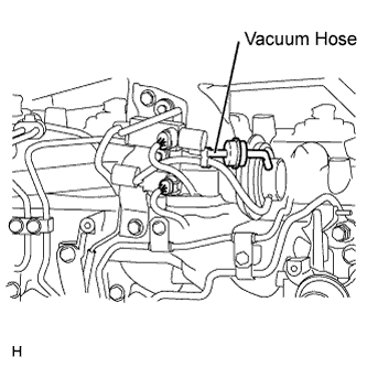 |
Disconnect the vacuum hose from the electric EGR control valve assembly.
Start the engine.
Check if there is suction from the vacuum hose during idling.
|
| ||||
| OK | |
|
| 7.REMOVE DEPOSIT (ELECTRIC EGR CONTROL VALVE ASSEMBLY) |
Remove the electric EGR control valve assembly (Click here).
Visually check the electric EGR control valve assembly for deposits. If there are deposits, clean the electric EGR control valve assembly.
Reinstall the electric EGR control valve assembly (Click here).
|
| ||||
| 8.REPAIR OR REPLACE VACUUM HOSE |
Repair or replace of the EGR valve system vacuum hose.
|
| ||||
| 9.READ VALUE USING INTELLIGENT TESTER (INJECTION VOLUME) |
Connect the intelligent tester to the DLC3.
Start the engine and warm it up until the engine coolant temperature reaches 70°C (158°F) or higher.
Allow the engine to idle for 1 minute or more.
Turn the tester on.
Enter the following menus: Powertrain / Engine and ECT / Data List / Injection Volume.
Read the values during engine idling.
| Result | Proceed to |
| Injection Volume is less than 5 mm3/st | A |
| Except above | B |
|
| ||||
| A | |
|
| 10.REPLACE INJECTOR ASSEMBLIES OF ALL CYLINDERS |
Replace the injector assemblies (Click here).
| NEXT | |
|
| 11.BLEED AIR FROM FUEL SYSTEM |
Bleed the air from the fuel system .
| NEXT | |
|
| 12.REGISTER INJECTOR COMPENSATION CODE AND PERFORM PILOT QUANTITY LEARNING |
Register the injector compensation code .
Perform the injector pilot quantity learning .
| NEXT | |
|
| 13.CONFIRM WHETHER MALFUNCTION HAS BEEN SUCCESSFULLY REPAIRED |
Connect the intelligent tester to the DLC3.
Clear the DTCs (Click here).
Turn the ignition switch off.
Start the engine and warm it up.
Confirm the value of Engine Speed from the Freeze Frame Data recorded previously, and then drive the vehicle according to the Engine Speed value.
Read the DTCs.
| Result | Proceed to |
| P1251 is not output and the amount by which MAP exceeds Target Boost Pressure is 20 kPa or less | A |
| Except above | B* |
|
| ||||
| A | ||
 | ||
| ||
| 14.CHECK HARNESS AND CONNECTOR (TURBO MOTOR DRIVER - TURBOCHARGER SUB-ASSEMBLY) |
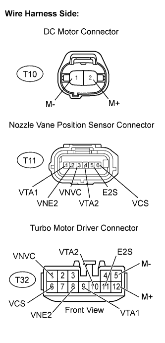 |
Disconnect the T10 DC motor connector.
Disconnect the T11 nozzle vane position sensor connector.
Disconnect the T32 turbo motor driver connector.
Measure the resistance according to the value(s) in the table below.
| Tester Connection | Condition | Specified Condition |
| M+ (T10-2) - M+ (T32-12) | Always | Below 1 Ω |
| M- (T10-1) - M- (T32-5) | Always | Below 1 Ω |
| VTA1 (T11-1) - VTA1 (T32-9) | Always | Below 1 Ω |
| VNE2 (T11-2) - VNE2 (T32-8) | Always | Below 1 Ω |
| VNVC (T11-3) - VNVC (T32-1) | Always | Below 1 Ω |
| VTA2 (T11-4) - VTA2 (T32-10) | Always | Below 1 Ω |
| E2S (T11-5) - E2S (T32-11) | Always | Below 1 Ω |
| VCS (T11-6) - VCS (T32-6) | Always | Below 1 Ω |
| Tester Connection | Condition | Specified Condition |
| M+ (T10-2) or M+ (T32-12) - Body ground | Always | 10 kΩ or higher |
| M- (T10-1) or M- (T32-5) - Body ground | Always | 10 kΩ or higher |
| VTA1 (T11-1) or VTA1 (T32-9) - Body ground | Always | 10 kΩ or higher |
| VNE2 (T11-2) or VNE2 (T32-8) - Body ground | Always | 10 kΩ or higher |
| VNVC (T11-3) or VNVC (T32-1) - Body ground | Always | 10 kΩ or higher |
| VTA2 (T11-4) or VTA2 (T32-10) - Body ground | Always | 10 kΩ or higher |
| E2S (T11-5) or E2S (T32-11) - Body ground | Always | 10 kΩ or higher |
| VCS (T11-6) or VCS (T32-6) - Body ground | Always | 10 kΩ or higher |
Reconnect the T10 DC motor connector.
Reconnect the T11 nozzle vane position sensor connector.
Reconnect the T32 turbo motor driver connector.
|
| ||||
| OK | ||
| ||
| ||
