 |
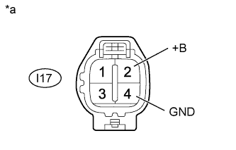
Disconnect the injector driver connectors.
ECD SYSTEM (for i-ART) > Injector Circuit |
| 1.CHECK INJECTOR DRIVER (POWER SOURCE) |
|
Disconnect the injector driver connectors.
Measure the voltage according to the value(s) in the table below.
| Tester Connection | Switch Condition | Specified Condition |
| I17-2 (+B) - I17-4 (GND) | Ignition switch ON | 11 to 14 V |
| *a | Front view of wire harness connector (to Injector Driver) |
Reconnect the injector driver connectors.
|
| ||||
| NG | |
 |
| 2.INSPECT NO. 1 INTEGRATION RELAY (EDU RELAY) |
Inspect the No. 1 integration relay (EDU relay) .
|
| ||||
| OK | |
|
| 3.CHECK HARNESS AND CONNECTOR (INJECTOR DRIVER - NO. 1 INTEGRATION RELAY) |
Remove the No. 1 integration relay from the engine room relay block and junction block assembly.
Disconnect the injector driver connector.
Disconnect the ECM connector.
Measure the resistance according to the value(s) in the table below.
| Tester Connection | Condition | Specified Condition |
| I17-2 (+B) - 1J-8 | Always | Below 1 Ω |
| I17-4 (GND) - Body ground | Always | Below 1 Ω |
| 1J-5 - 1J-6 | Always | Below 1 Ω |
| I17-2 (+B) or 1J-8 - Body ground | Always | 10 kΩ or higher |
| 1J-5 or 1J-6 - Body ground | Always | 10 kΩ or higher |
Reconnect the injector driver connector.
Reinstall the No. 1 integration relay.
|
| ||||
| OK | |
|
| 4.CHECK HARNESS AND CONNECTOR (ECM - NO. 1 INTEGRATION RELAY) |
Remove the No. 1 integration relay from the engine room relay block and junction block assembly.
Disconnect the ECM connector.
Measure the resistance according to the value(s) in the table below.
| Tester Connection | Condition | Specified Condition |
| E31-12 (IREL) - 1J-7 | Always | Below 1 Ω |
| E31-12 (IREL) or 1J-7 - Body ground | Always | 10 kΩ or higher |
Reconnect the ECM connector.
Reinstall the No. 1 integration relay.
|
| ||||
| OK | ||
 | ||
| ||
