| B |  |
| PROCEED TO NEXT SUSPECTED AREA SHOWN IN PROBLEM SYMPTOMS TABLE (Click here) |
| C | |
| RETURN TO ORIGINAL INSPECTION FLOW BECAUSE CHECK RESULT IS NORMAL |
SFI SYSTEM > Sub Tank Fuel Pump Control Circuit |
| 1.PERFORM ACTIVE TEST USING INTELLIGENT TESTER (SUB FUEL TANK VSV) |
Connect the intelligent tester to the DLC3.
Turn the ignition switch to ON.
Turn the tester on.
Enter the following menus: Powertrain / Engine and ECT / Active Test / Sub Fuel Tank VSV.
Check whether the sub tank fuel pump operation sound occurs when performing the Active Test on the tester.
| Condition | Proceed to |
| NG | A |
| OK (When troubleshooting according to Problem Symptoms Table) | B |
| OK (When troubleshooting according to DTC chart) | C |
|
| ||||
|
| ||||
| A | |
 |
| 2.INSPECT FFV RELAY |
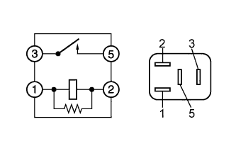 |
Remove the FFV relay from the engine room relay block.
Measure the resistance according to the value(s) in the table below.
| Tester Connection | Condition | Specified Condition |
| 3 - 5 | Battery voltage is not applied between terminals 1 and 2 | 10 kΩ or higher |
| 3 - 5 | Battery voltage is applied between terminals 1 and 2 | Below 1 Ω |
Reinstall the FFV relay.
|
| ||||
| OK | |
|
| 3.CHECK HARNESS AND CONNECTOR (FFV RELAY - IGN FUSE) |
Remove the FFV relay from the engine room relay block.
Remove the IGN fuse from the instrument panel junction block.
Measure the resistance according to the value(s) in the table below.
| Tester Connection | Condition | Specified Condition |
| FFV relay terminal (2) - IGN fuse terminal (2) | Always | Below 1 Ω |
Reinstall the IGN fuse.
Reinstall the FFV relay.
|
| ||||
| OK | |
|
| 4.CHECK HARNESS AND CONNECTOR (FFV RELAY - INTEGRATION RELAY) |
Remove the FFV relay from the engine room relay block.
Remove the integration relay from the engine room relay block.
Disconnect the integration relay connector.
Measure the resistance according to the value(s) in the table below.
| Tester Connection | Condition | Specified Condition |
| FFV relay terminal (5) - 1J-5 | Always | Below 1 Ω |
| Tester Connection | Condition | Specified Condition |
| FFV relay terminal (5) or 1J-5 - Body ground | Always | 10 kΩ or higher |
Reinstall the FFV relay.
Reconnect the integration relay connector.
Reinstall the integration relay.
|
| ||||
| OK | |
|
| 5.CHECK HARNESS AND CONNECTOR (ECM - FFV RELAY) |
Disconnect the ECM connector.
Remove the FFV relay from the engine room relay block.
Measure the resistance according to the value(s) in the table below.
| Tester Connection | Condition | Specified Condition |
| E25-11 (FFR) - FFV relay terminal (1) | Always | Below 1 Ω |
| Tester Connection | Condition | Specified Condition |
| E25-11 (FFR) or FFV relay terminal (1) - Body ground | Always | 10 kΩ or higher |
Reinstall the FFV relay.
Reconnect the ECM connector.
|
| ||||
| OK | |
|
| 6.CHECK HARNESS AND CONNECTOR (FFV RELAY - FUEL PUMP (FOR FUEL SUB TANK)) |
Remove the FFV relay from the engine room relay block.
Disconnect the fuel pump (for fuel sub tank) connector.
Measure the resistance according to the value(s) in the table below.
| Tester Connection | Condition | Specified Condition |
| FFV relay terminal (3) - F25-1 | Always | Below 1 Ω |
| Tester Connection | Condition | Specified Condition |
| FFV relay terminal (3) or F25-1 - Body ground | Always | 10 kΩ or higher |
Reconnect the fuel pump (for fuel sub tank) connector.
Reinstall the FFV relay.
|
| ||||
| OK | |
|
| 7.INSPECT FUEL PUMP (FOR FUEL SUB TANK) |
Inspect the fuel pump (for fuel sub tank) (Click here).
|
| ||||
| OK | |
|
| 8.CHECK HARNESS AND CONNECTOR (FUEL PUMP (FOR FUEL SUB TANK) - BODY GROUND) |
Disconnect the fuel pump (for fuel sub tank) connector.
Measure the resistance according to the value(s) in the table below.
| Tester Connection | Condition | Specified Condition |
| F25-1 - Body ground | Always | Below 1 Ω |
Reconnect the fuel pump (for fuel sub tank) connector.
|
| ||||
| OK | |
|
| 9.CHECK HARNESS AND CONNECTOR (ECM - BODY GROUND) |
Disconnect the ECM connector.
Measure the resistance according to the value(s) in the table below.
| Tester Connection | Condition | Specified Condition |
| E23-11 (E01) - Body ground | Always | Below 1 Ω |
Reconnect the ECM connector.
|
| ||||
| OK | ||
 | ||
| ||