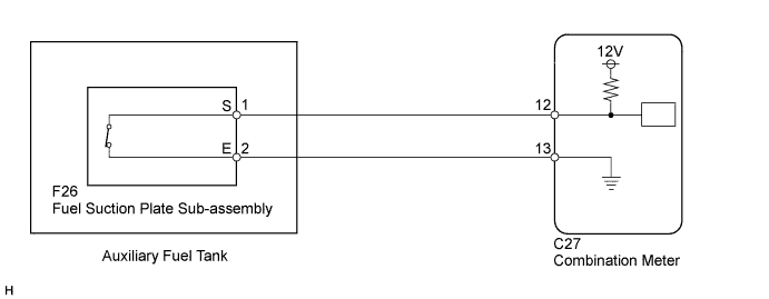
METER / GAUGE SYSTEM > Auxiliary Fuel Tank Warning Light Circuit |
| 1.INSPECT COMBINATION METER (OUTPUT VOLTAGE) |
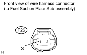 |
Disconnect the F26 connector.
Measure the voltage according to the value(s) in the table below.
| Tester Connection | Condition | Specified Condition |
| F26-1 (S) - Body ground | Ignition switch ON | 11 to 14 V |
|
| ||||
| OK | |
 |
| 2.CHECK HARNESS AND CONNECTOR (COMBINATION METER - FUEL SUCTION PLATE SUB-ASSEMBLY) |
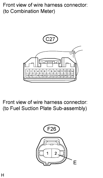 |
Disconnect the C27 connector.
Measure the resistance according to the value(s) in the table below.
| Tester Connection | Condition | Specified Condition |
| C27-13 - F26-2 (E) | Always | Below 1 Ω |
| C27-13 - Body ground | Always | 10 kΩ or higher |
|
| ||||
| OK | |
|
| 3.INSPECT FUEL SUCTION PLATE SUB-ASSEMBLY |
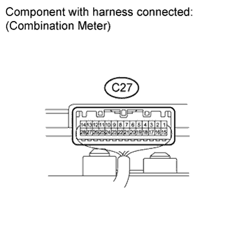 |
Reconnect the F26 and C27 connector.
Measure the voltage according to the value(s) in the table below.
| Tester Connection | Condition | Specified Condition |
| C27-12 - C27-13 | Ignition switch ON, auxiliary tank is empty (Auxiliary tank warning light comes on) | Below 6.5 V |
| C27-12 - C27-13 | Ignition switch ON, auxiliary tank is full (Auxiliary tank warning light goes off) | 6.6 V or higher |
|
| ||||
| OK | ||
 | ||
| ||
| 4.CHECK HARNESS AND CONNECTOR (COMBINATION METER - FUEL SUCTION PLATE SUB-ASSEMBLY) |
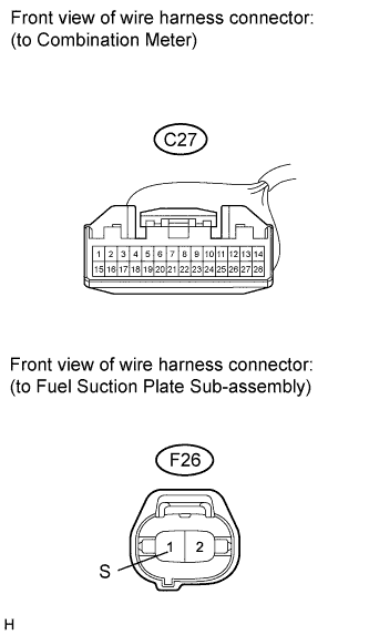 |
Disconnect the C27 connector.
Measure the resistance according to the value(s) in the table below.
| Tester Connection | Condition | Specified Condition |
| C27-12 - F26-1 (S) | Always | Below 1 Ω |
| C27-12 (L) - Body ground | Always | 10 kΩ or higher |
|
| ||||
| OK | ||
| ||
| ||

