 |
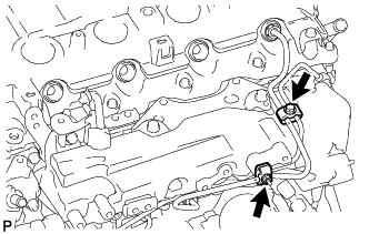
Remove the bolt, nut and 2 No. 2 injection pipe clamps.
INTAKE MANIFOLD (w/ Glow Plug Controller) > REMOVAL |
| 1. PRECAUTION |
| 2. DISCONNECT CABLE FROM NEGATIVE BATTERY TERMINAL |
| 3. REMOVE ELECTRIC EGR CONTROL VALVE ASSEMBLY WITH NO. 2 EGR VALVE AND EGR COOLER |
| 4. REMOVE NO. 4 INJECTION PIPE SUB-ASSEMBLY |
|
Remove the bolt, nut and 2 No. 2 injection pipe clamps.
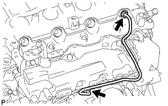 |
Using a 17 mm union nut wrench, loosen the union nuts and remove the No. 4 injection pipe.
| 5. REMOVE WIRING HARNESS CLAMP BRACKET |
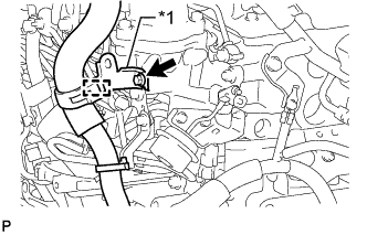 |
Detach the wire harness clamp.
| *1 | Wiring Harness Clamp Bracket |
Remove the bolt and wiring harness clamp bracket.
| 6. REMOVE NO. 2 FUEL PIPE |
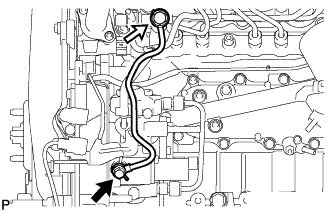 |
Using a 6 mm hexagon wrench, remove the supply pump hollow screw and gasket.
 | Supply Pump Hollow Screw |
 | Fuel Check Valve |
Remove the fuel check valve, No. 2 fuel pipe and gasket.
| 7. REMOVE NO. 3 NOZZLE LEAKAGE PIPE |
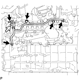 |
Disconnect the 3 fuel hoses.
| Fuel Check Valve |
Remove the 2 bolts.
Remove the fuel check valve, gasket and No. 3 nozzle leakage pipe.
| 8. REMOVE NO. 2 NOZZLE LEAKAGE PIPE ASSEMBLY |
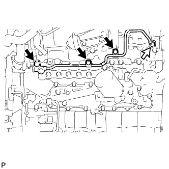 |
Remove the 3 bolts.
| Union Bolt |
Remove the union bolt, gasket and No. 2 nozzle leakage pipe.
| 9. REMOVE GLOW CONNECTOR BRACKET |
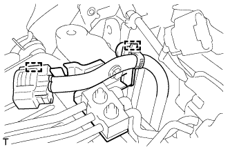 |
Disconnect the No. 1 glow plug connector and detach the clamp.
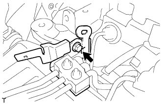 |
Remove the bolt and glow connector bracket.
| 10. REMOVE NO. 3 INTERCOOLER SUPPORT BRACKET |
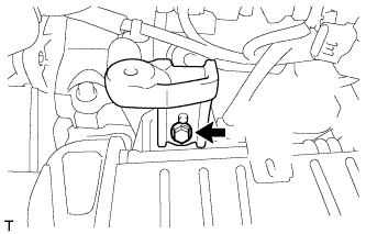 |
Remove the bolt and No. 3 intercooler support bracket.
| 11. REMOVE NO. 2 MANIFOLD STAY |
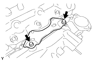 |
Remove the bolt and No. 2 manifold stay.
| 12. REMOVE NO. 1 GLOW PLUG CONNECTOR |
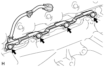 |
Remove the 4 screw grommets.
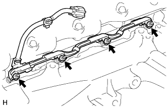 |
Remove the 4 nuts and No. 1 glow plug connector.
| 13. REMOVE NO. 1 INTAKE MANIFOLD INSULATOR |
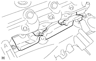 |
| 14. REMOVE INTAKE MANIFOLD INSULATOR |
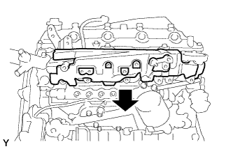 |
| 15. REMOVE VACUUM CONTROL VALVE SET |
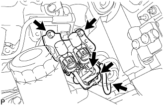 |
Disconnect the 2 vacuum switching valve connectors and 3 vacuum hoses.
Remove the 2 bolts and vacuum control valve set.
| 16. REMOVE VACUUM SWITCHING VALVE ASSEMBLY |
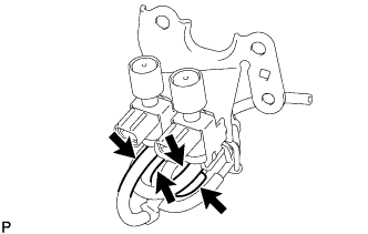 |
Disconnect the 4 vacuum hoses.
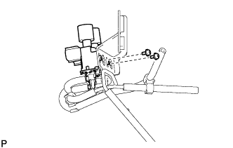 |
Remove the 2 screws, No. 1 vacuum switching valve and No. 2 vacuum switching valve.
| 17. REMOVE INTAKE MANIFOLD |
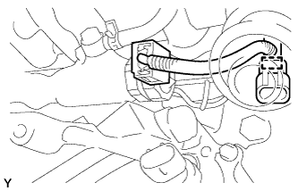 |
Detach the sensor wire connector clamp from the intake manifold.
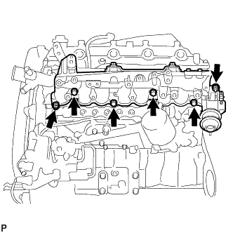 |
Remove the 4 bolts, 2 nuts, intake manifold and gasket.