1GR-FE INTAKE / EXHAUST INTAKE MANIFOLD INSTALLATION
PROCEDURE

 1.INSTALL STUD BOLT
- NOTICE:
-
If a stud bolt is deformed or its threads are damaged, replace it.
Using an E7 "TORX" socket wrench, install the 2 stud bolts to the intake manifold.
- Torque:
- 8.0 N*m (82 kgf*cm, 71 in.*lbf)
17111
2.INSTALL INTAKE MANIFOLD
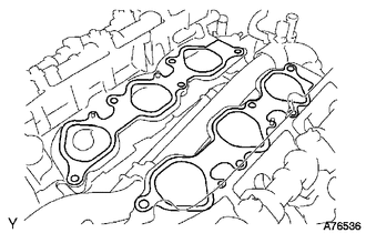
Set 2 new gaskets on each cylinder head.
- NOTICE:
- ·
Align the port holes of the gasket and cylinder head.
- ·
Make sure the gaskets are installed facing the proper direction.
Set the intake manifold on the cylinder heads.
Install and uniformly tighten the 10 bolts in several passes.
- Torque:
- 26 N*m (265 kgf*cm, 19 ft.*lbf)
- HINT:
-
Tighten the inner installation bolts of the intake manifold before tightening the outer bolts.
23807
3.INSTALL FUEL DELIVERY PIPE SUB-ASSEMBLY
23802B
4.CONNECT NO. 2 FUEL PIPE SUB-ASSEMBLY
23801P
5.CONNECT NO. 1 FUEL PIPE SUB-ASSEMBLY
17129
6.INSTALL INTAKE AIR SURGE TANK
- NOTICE:
- Do not apply oil to the bolts and nuts listed below: :
Oil Application Prohibited Bolts for surge tank and intake manifold Nuts for surge tank and intake manifold
Install a new gasket to the intake air surge tank.
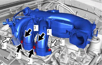

|
Bolt |

|
Nut |
Using an 8 mm hexagon wrench, install the intake air surge tank with the 4 bolts and 2 nuts. Tighten the bolts and nuts in the order shown in the illustration.
- Torque:
- 28 N*m (286 kgf*cm, 21 ft.*lbf)
Install the No. 2 surge tank stay with the 2 bolts.
- Torque:
- 21 N*m (214 kgf*cm, 15 ft.*lbf)
Install the No. 1 surge tank stay with the 2 bolts.
- Torque:
- 21 N*m (214 kgf*cm, 15 ft.*lbf)
Install the oil baffle plate with the bolt.
- Torque:
- 9.0 N*m (92 kgf*cm, 80 in.*lbf)
Install the throttle body bracket with the 2 bolts.
- Torque:
- 21 N*m (214 kgf*cm, 15 ft.*lbf)
Connect the water hose sub-assembly to the intake air surge tank with the 2 bolts.
- Torque:
- 5.4 N*m (55 kgf*cm, 48 in.*lbf)
Attach the 2 wire harness clamps.
Connect the purge line hose to the intake air surge tank, and slide the clip to secure the hose.
Connect the No. 1 PCV hose to the intake air surge tank, and slide the clip to secure the hose.
Attach the 2 wire harness clamps and connect the connector.
Connect the connector and attach the wire harness clamp.
Connect the fuel vapor feed hose to the purge VSV, and slide the clip to secure the hose.
Connect the throttle body with motor connector.
Connect the No. 5 water by-pass hose to the throttle body with motor assembly, and slide the clip to secure the hose.
Connect the No. 4 water by-pass hose to the throttle body with motor assembly, and slide the clip to secure the hose.
7.INSTALL V-BANK COVER BRACKET
Install the V-bank cover bracket with the 2 bolts.
- Torque:
- 9.0 N*m (92 kgf*cm, 80 in.*lbf)
17705
8.INSTALL AIR CLEANER CAP SUB-ASSEMBLY WITH NO. 1 AIR CLEANER HOSE
9.ADD ENGINE COOLANT
10.INSPECT FOR COOLANT LEAK
11.INSPECT FOR FUEL LEAK
11259
12.INSTALL V-BANK COVER