2TR-FE INTAKE / EXHAUST INTAKE MANIFOLD INSTALLATION
PROCEDURE

 17111
1.INSTALL INTAKE MANIFOLD
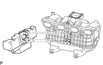
Install the intake manifold insulator to the intake manifold.
- HINT:
-
Insert the protrusions of the intake manifold insulator into the grille of the intake manifold.
- NOTICE:
-
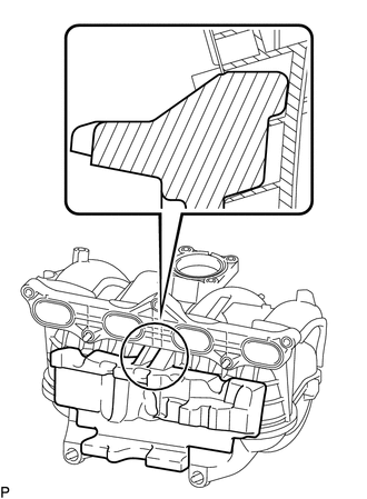
-
Insert the intake manifold insulator until the protrusion of the line as shown in the illustration.
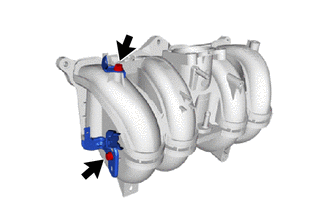
for LHD:
Install the 2 wire harness clamp brackets to the intake manifold with the 2 bolts.
- Torque:
- 13 N*m (133 kgf*cm, 10 ft.*lbf)
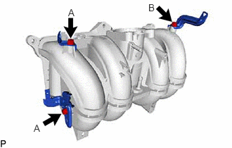
for RHD:
Install the 3 wire harness clamp brackets to the intake manifold with the 3 bolts.
- Torque:
- for bolt A : 13 N*m (133 kgf*cm, 10 ft.*lbf)
- for bolt B : 30 N*m (306 kgf*cm, 22 ft.*lbf)
Install a new gasket to the intake manifold.
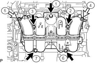

|
Bolt |

|
Nut |
Temporarily install the intake manifold with the 5 bolts and 2 nuts, and then tighten the bolts and nuts in the sequence shown in the illustration.
- Torque:
- 25 N*m (255 kgf*cm, 18 ft.*lbf)
Install the 2 No. 2 intake manifold insulators to the intake manifold.
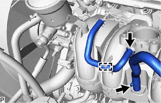
Install the purge line hose to the intake manifold, and slide the clip to secure the hose.
Attach the clamp.
Connect the union to connector tube hose to the intake manifold, and slide the clip to secure the hose.
Connect the No. 3 PCV hose to the intake manifold, and slide the clip to secure the hose.
Attach the No. 2 water by-pass hose to the intake manifold.
Connect the heater water pipe sub-assembly to the intake manifold with the bolt.
- Torque:
- 5.4 N*m (55 kgf*cm, 48 in.*lbf)
for RHD:
Attach the engine wire harness clamp.
Attach the No. 1 fuel hose to the intake manifold.
Attach the 4 wire harness clamps to the 2 wire harness clamp brackets.
17650G
2.INSTALL PURGE VSV
53882F
3.INSTALL FRONT FENDER SEAL LH
22030
4.INSTALL THROTTLE BODY WITH MOTOR ASSEMBLY