VF2CM TRANSFER / 4WD / AWD TOUCH SELECT 2-4 AND HIGH-LOW SYSTEM 4WD Control Switch Circuit
WIRING DIAGRAM
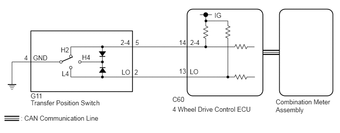
PROCEDURE
Confirm the problem symptoms.
- Result:
Result Proceed to The 4WD indicator light (green) and 4LO indicator light remain off A The 4WD indicator light (green) remains illuminated, and the 4LO indicator light remains off B The 4WD indicator light (green) and 4LO indicator light remain illuminated C
A
B
C
Turn the ignition switch to ON.
for Automatic Transmission:
Move the shift lever to N.
for Manual Transmission:
Depress the clutch pedal.
Turn the transfer position switch to H4.
Wait for 60 seconds.
Check the 4WD indicator light (green).
- Result:
Result Proceed to The 4WD indicator light (green) blinks*1 or illuminates A The 4WD indicator light (green) rapidly blinks*2 or remains off B
*1 (Blinking): Blinks at 0.5 second intervals (0.5 seconds on and 0.5 seconds off)
*2 (Rapidly blinking): Blinks at 0.25 second intervals (0.25 seconds on and 0.25 seconds off)
A
B
Turn the transfer position switch to L4.
Check if DTC P279E is output after 60 seconds elapse.
Click hereDrivetrain>VF2CM TRANSFER / 4WD / AWD>TOUCH SELECT 2-4 AND HIGH-LOW SYSTEM>DTC CHECK / CLEAR
- Result:
Result Proceed to DTC P279E is not output A DTC P279E is output B
A
B
Select "Bus Check" from the System Selection Menu screen, and follow the prompts on the screen to inspect the CAN Bus.
for LHD: Click herePower Source / Network>NETWORKING>CAN COMMUNICATION SYSTEM(for LHD)>DIAGNOSIS SYSTEM
for RHD: Click herePower Source / Network>NETWORKING>CAN COMMUNICATION SYSTEM(for RHD)>DIAGNOSIS SYSTEM
- OK:
"Bus Check" indicates no malfunctions in CAN communication.
- Result:
Proceed to OK NG
OK
NG
for LHD: Click herePower Source / Network>NETWORKING>CAN COMMUNICATION SYSTEM(for LHD)>HOW TO PROCEED WITH TROUBLESHOOTING
for RHD: Click herePower Source / Network>NETWORKING>CAN COMMUNICATION SYSTEM(for RHD)>HOW TO PROCEED WITH TROUBLESHOOTING
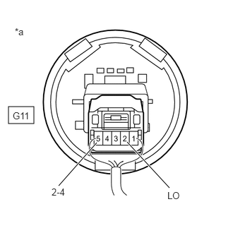
| *a | Component with harness connected
(Transfer Position Switch) |
Remove the transfer position switch with its connector still connected.
Measure the voltage according to the value(s) in the table below.
- Standard Voltage:
Tester Connection Switch Condition Specified Condition G11-5 (2-4) - Body ground Ignition switch ON
H2 positionBelow 1.5 V Ignition switch ON
H4 positionBelow 1.5 V Ignition switch ON
L4 position10 to 14 V G11-2 (LO) - Body ground Ignition switch ON
H2 position10 to 14 V Ignition switch ON
H4 positionBelow 1.5 V Ignition switch ON
L4 positionBelow 1.5 V
- Result:
Proceed to OK NG
OK
Click hereVehicle Interior>METER / GAUGE / DISPLAY>METER / GAUGE SYSTEM>HOW TO PROCEED WITH TROUBLESHOOTING
NG
Turn the ignition switch to ON.
for Automatic Transmission:
Move the shift lever to N.
for Manual Transmission:
Depress the clutch pedal.
Turn the transfer position switch to H2.
Wait for 60 seconds.
Check the 4WD indicator light (green).
- Result:
Result Proceed to The 4WD indicator light (green) blinks*1 or turns off A The 4WD indicator light (green) rapidly blinks*2 or remains on B
*1 (Blinking): Blinks at 0.5 second intervals (0.5 seconds on and 0.5 seconds off)
*2 (Rapidly blinking): Blinks at 0.25 second intervals (0.25 seconds on and 0.25 seconds off)
A
B
- HINT:
-
Perform the following procedures with the vehicle stopped.
Turn the ignition switch to ON.
for Automatic Transmission:
Move the shift lever to N.
for Manual Transmission:
Depress the clutch pedal.
Turn the transfer position switch to H4.
Wait for 60 seconds.
Check the 4LO indicator light.
- Result:
Result Proceed to The 4LO indicator light blinks*1 or turns off A The 4LO indicator light rapidly blinks*2 or remains on B
*1 (Blinking): Blinks at 0.5 second intervals (0.5 seconds on and 0.5 seconds off)
*2 (Rapidly blinking): Blinks at 0.25 second intervals (0.25 seconds on and 0.25 seconds off)
A
B
Turn the transfer position switch to H2.
Check if DTC P279E is output after 60 seconds elapse.
Click hereDrivetrain>VF2CM TRANSFER / 4WD / AWD>TOUCH SELECT 2-4 AND HIGH-LOW SYSTEM>DTC CHECK / CLEAR
- Result:
Result Proceed to DTC P279E is not output A DTC P279E is output B
A
B
| *a | Component with harness connected
(Transfer Position Switch) |
Remove the transfer position switch with its connector still connected.
Measure the voltage according to the value(s) in the table below.
- Standard Voltage:
Tester Connection Switch Condition Specified Condition G11-5 (2-4) - Body ground Ignition switch ON
H2 positionBelow 1.5 V Ignition switch ON
H4 positionBelow 1.5 V Ignition switch ON
L4 position10 to 14 V G11-2 (LO) - Body ground Ignition switch ON
H2 position10 to 14 V Ignition switch ON
H4 positionBelow 1.5 V Ignition switch ON
L4 positionBelow 1.5 V
- Result:
Proceed to OK NG
OK
for LHD: Click herePower Source / Network>NETWORKING>CAN COMMUNICATION SYSTEM(for LHD)>HOW TO PROCEED WITH TROUBLESHOOTING
for RHD: Click herePower Source / Network>NETWORKING>CAN COMMUNICATION SYSTEM(for RHD)>HOW TO PROCEED WITH TROUBLESHOOTING
NG