INTERIOR PANELS / TRIM FRONT CONSOLE BOX INSTALLATION
CAUTION / NOTICE / HINT
- HINT:
- ·
Use the same procedure for RHD and LHD vehicles.
·The procedure listed below is for LHD vehicles.
·A bolt without a torque specification is shown in the standard bolt chart.
Click hereGeneral>SPECIFICATIONS>STANDARD BOLT>SPECIFIED TORQUE FOR STANDARD BOLTS
PROCEDURE

 58810J
1.INSTALL CONSOLE BOX ASSEMBLY
for Automatic Transmission:
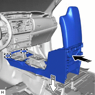

|
Install in this Direction (1) |

|
Install in this Direction (2) |
Attach the guide to install the console box assembly as shown in the illustration.
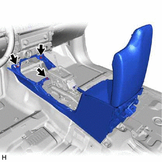
Install the 3 screws.
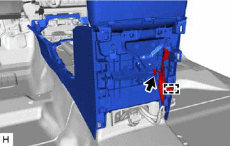
Connect the connector and attach the clamp.
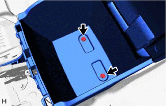
Install the 2 bolts.
for Manual Transmission:
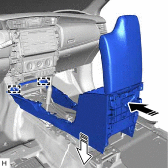
|
|
Install in this Direction (1) |
|
|
Install in this Direction (2) |
Attach the guide to install the console box assembly as shown in the illustration.
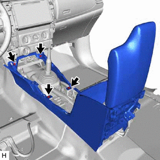
Install the 4 screws.
Connect the connector and attach the clamp.
Install the 2 bolts.
58815B
2.INSTALL CONSOLE BOX CARPET
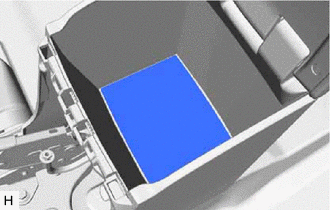
Install the console box carpet.
58903A
3.INSTALL REAR CONSOLE END PANEL SUB-ASSEMBLY
Connect the connector.
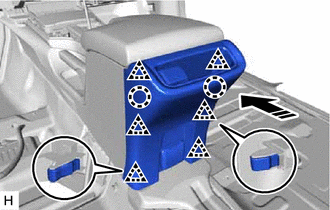
|
|
Install in this Direction |
Attach the claw and clip to install the rear console end panel sub-assembly as shown in the illustration.
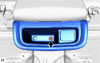
Install the screw.
58916
4.INSTALL BOX BOTTOM MAT
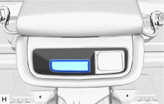
Install the box bottom mat.
58804A
5.INSTALL UPPER CONSOLE PANEL SUB-ASSEMBLY
for Automatic Transmission:
Connect the connector.
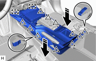
|
|
Install in this Direction |
Attach the guide and clip to install the upper console panel sub-assembly as shown in the illustration.
for Manual Transmission:
Connect the connector.
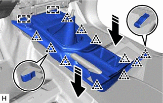
|
|
Install in this Direction |
Attach the guide and clip to install the upper console panel sub-assembly as shown in the illustration.
58808
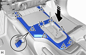
6.INSTALL SHIFTING HOLE COVER SUB-ASSEMBLY (for Automatic Transmission)
|
|
Install in this Direction |
Attach the claw and clip to install the shifting hole cover sub-assembly as shown in the illustration.
33504F
7.INSTALL SHIFT LEVER KNOB SUB-ASSEMBLY
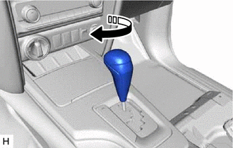
for Automatic Transmission:
|
|
Install in this Direction |
Install the shift lever knob sub-assembly and twist it as shown in the illustration.
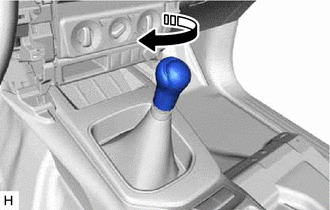
for Manual Transmission:
|
|
Install in this Direction |
Install the shift lever knob sub-assembly and twist it as shown in the illustration.
|
|
Install in this Direction |
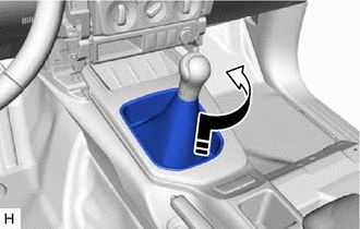
Connect the shifting hole cover and twist it as shown in the illustration.
55012A
8.INSTALL NO. 2 INSTRUMENT PANEL GARNISH SUB-ASSEMBLY
55011A
9.INSTALL NO. 1 INSTRUMENT PANEL GARNISH SUB-ASSEMBLY
55667
10.INSTALL INSTRUMENT PANEL REGISTER BEZEL GARNISH