1TR-FE FUEL FUEL TANK(for Long Wheelbase) INSTALLATION
PROCEDURE

 77213B
1.INSTALL FUEL TANK TO FILLER PIPE HOSE
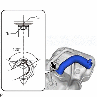
| *a | Protrusion |
| *b | Paint Mark (White) |
Install the fuel tank to filler pipe hose to the fuel tank assembly, and tighten the clamp to secure the hose.
- HINT:
-
Make sure the hose clamp is oriented as shown in the illustration.
77020A
2.INSTALL FUEL SUCTION WITH PUMP AND GAUGE TUBE ASSEMBLY
3.INSTALL FUEL TANK CLAMP
77651B
4.INSTALL FUEL TANK CUSHION
Install the 2 fuel tank cushions to the fuel tank assembly.
77697
5.INSTALL NO. 1 FUEL TANK HEAT INSULATOR
Install the No. 1 fuel tank heat insulator with the 4 No. 2 fuel tank brackets.
Install the nut.
- Torque:
- 5.5 N*m (56 kgf*cm, 49 in.*lbf)
77001A
6.INSTALL FUEL TANK ASSEMBLY
Set the fuel tank assembly on an engine lifter and raise the fuel tank assembly.
- NOTICE:
-
Do not allow the fuel tank assembly to contact the vehicle, especially the differential.
Fold back approximately half of each cushion so that the wire harness can be installed in the step below.
Attach the wire harness to the 6 clamps and connect the fuel sender gauge assembly connector.
- NOTICE:
-
Be careful not to cut the wire harness.
Install the 2 fuel tank bands with the 2 fuel tank band pins and 2 clips.
Install the 2 fuel tank bands with the 2 bolts.
- Torque:
- 45 N*m (459 kgf*cm, 33 ft.*lbf)
77213B
7.CONNECT FUEL TANK TO FILLER PIPE HOSE
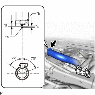
| *a | Protrusion |
| *b | Paint Mark (Yellow) |
| *c | 0 to 3 mm (0 to 0.118 in.) |
| *d | 2 to 7 mm (0.0787 to 0.276 in.) |
Connect the fuel tank to filler pipe hose to the fuel tank filler pipe sub-assembly, and tighten the clamp to secure the hose.
- HINT:
-
Make sure the hose clamp is oriented as shown in the illustration.
8.CONNECT FUEL TANK BREATHER HOSE
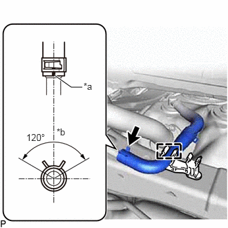
| *a | Paint Mark |
| *b | Top of Vehicle |
Connect the fuel tank breather hose to the fuel tank filler pipe sub-assembly, and slide the clamp to secure the hose.
- HINT:
-
Make sure the hose clamp is oriented as shown in the illustration.
Attach the fuel tank breather hose to the clamp.
77251B
9.CONNECT FUEL TUBE
Connect the fuel tank main tube sub-assembly and fuel tank return tube, vent line tube.
Click hereEngine / Hybrid System>1TR-FE FUEL>FUEL SYSTEM>PRECAUTION
77289B
10.INSTALL NO. 3 FUEL TUBE CLAMP
Install the No. 3 fuel tube clamp to the fuel tube.
77641A
11.INSTALL NO. 1 FUEL TANK PROTECTOR
Install the No. 1 fuel tank protector to the fuel tank assembly with the 5 nuts.
- Torque:
- 13 N*m (133 kgf*cm, 10 ft.*lbf)
77310A
12.INSTALL FUEL TANK CAP ASSEMBLY
13.CONNECT CABLE TO NEGATIVE BATTERY TERMINAL
- NOTICE:
-
When disconnecting the cable, some systems need to be initialized after the cable is reconnected.
-
Click hereGeneral>INTRODUCTION>REPAIR INSTRUCTION>INITIALIZATION
14.INSPECT FOR FUEL LEAK