NAVIGATION / MULTI INFO DISPLAY NAVIGATION RECEIVER INSTALLATION
CAUTION / NOTICE / HINT
- HINT:
- ·
Use the same procedure for RHD and LHD vehicles.
·The procedure listed below is for LHD vehicles.
PROCEDURE

 86120L
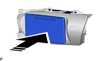
1.INSTALL NAVIGATION RECEIVER ASSEMBLY

|
Install in this Direction |
Insert the navigation receiver assembly in the direction of the arrow shown in the illustration to install it.
86212
2.INSTALL NO. 2 RADIO BRACKET
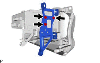
Install the No. 2 radio bracket to the navigation receiver assembly with the 3 screws.
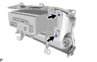
Install the 2 screws.
86211
3.INSTALL NO. 1 RADIO BRACKET
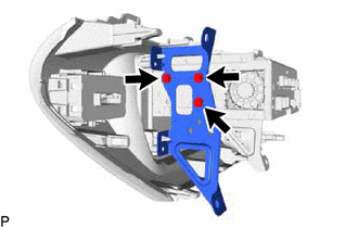
Install the No. 1 radio bracket to the navigation receiver assembly with the 3 screws.
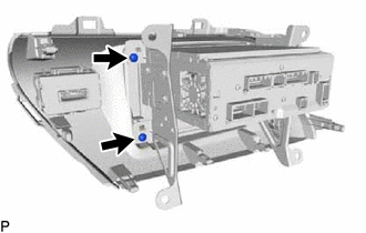
Install the 2 screws.
86120L
4.INSTALL NAVIGATION RECEIVER ASSEMBLY WITH BRACKET
Connect all the connectors.
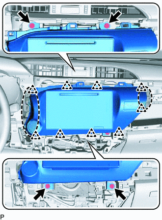

|
Place Hands Here |
Insert the navigation receiver assembly with bracket to attach the clips on its backside.
- NOTICE:
-
When inserting the navigation receiver assembly, do not press the knobs on it.
Install the navigation receiver assembly with bracket with the 4 screws.
55900
5.INSTALL AIR CONDITIONING CONTROL ASSEMBLY (for Automatic Air Conditioning System)
55909A
6.CONNECT AIR MIX DAMPER CONTROL CABLE SUB-ASSEMBLY (for Manual Air Conditioning System)
55908A
7.CONNECT AIR INLET DAMPER CONTROL CABLE SUB-ASSEMBLY (for Manual Air Conditioning System)
55906A
8.CONNECT DEFROSTER DAMPER CONTROL CABLE SUB-ASSEMBLY (for Manual Air Conditioning System)
84013A
9.INSTALL INTEGRATION PANEL SUB-ASSEMBLY WITH AIR CONDITIONING CONTROL ASSEMBLY (for Manual Air Conditioning System)
55918A
10.INSTALL AIR INLET DAMPER CONTROL LEVER (for Manual Air Conditioning System)
55905J
11.INSTALL CONTROL KNOB SUB-ASSEMBLY (for Manual Air Conditioning System)
55908A
12.CONNECT AIR INLET DAMPER CONTROL CABLE SUB-ASSEMBLY (for Manual Cooler System)
55906A
13.CONNECT DEFROSTER DAMPER CONTROL CABLE SUB-ASSEMBLY (for Manual Cooler System)
84013A
14.INSTALL INTEGRATION PANEL SUB-ASSEMBLY WITH AIR CONDITIONING CONTROL ASSEMBLY (for Manual Cooler System)
55918A
15.INSTALL AIR INLET DAMPER CONTROL LEVER (for Manual Cooler System)
55905J
16.INSTALL CONTROL KNOB SUB-ASSEMBLY (for Manual Cooler System)
55410C
17.INSTALL INSTRUMENT CLUSTER FINISH PANEL ASSEMBLY
55041B
18.INSTALL NO. 1 INSTRUMENT PANEL BOX DOOR SUB-ASSEMBLY
55470
19.INSTALL INSTRUMENT CLUSTER FINISH PANEL GARNISH ASSEMBLY
45100
20.INSTALL STEERING WHEEL ASSEMBLY
21.CONNECT CABLE TO NEGATIVE BATTERY TERMINAL
- NOTICE:
-
When disconnecting the cable, some systems need to be initialized after the cable is reconnected (See page General>INTRODUCTION>REPAIR INSTRUCTION>INITIALIZATION).