WIPER / WASHER WIPER AND WASHER SYSTEM Washer Fluid Level Warning Switch Circuit
DESCRIPTION
When the volume of washer fluid decreases to below a certain level (when the level warning switch assembly is turned on), the multi-information display warns the driver by displaying a message.
WIRING DIAGRAM
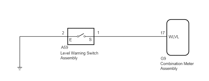
CAUTION / NOTICE / HINT
- NOTICE:
-
When replacing the combination meter assembly, make sure to replace it with a new one.
PROCEDURE
Read the Data List according to the display on the GTS.
Click hereVehicle Exterior>WIPER / WASHER>WIPER AND WASHER SYSTEM>DATA LIST / ACTIVE TEST
- Body Electrical > Combination Meter > Data List
-
Tester Display Measurement Item Range Normal Condition Diagnostic Note Washer Switch Level warning switch condition ON/OFF ON: Fluid volume is less than 600 to 800 cc (36.6 to 48.8 cu.in.)
OFF: Fluid volume is more than 600 to 800 cc (36.6 to 48.8 cu.in.)-
- Body Electrical > Combination Meter > Data List
-
Tester Display Washer Switch - 50003 122 32
- OK:
On the GTS screen, ON or OFF is displayed accordingly.
- Result:
Proceed to OK NG
OK
Click hereVehicle Interior>METER / GAUGE / DISPLAY>METER / GAUGE SYSTEM>HOW TO PROCEED WITH TROUBLESHOOTING
NG
Disconnect the A59 level warning switch assembly connector.
Inspect the level warning switch assembly.
Click hereVehicle Exterior>WIPER / WASHER>WASHER LEVEL WARNING SWITCH>INSPECTION
- Result:
Proceed to OK NG
OK
NG
Disconnect the A59 level warning switch assembly connector.
Disconnect the G9 combination meter assembly connector.
Measure the resistance according to the value(s) in the table below.
- Standard Resistance:
Tester Connection Condition Specified Condition A59-1 (S) - G9-17 (WLVL) Always Below 1 Ω A59-2 (E) - Body ground Always Below 1 Ω A59-1 (S) or G9-17 (WLVL) - Body ground Always 10 kΩ or higher
- Result:
Proceed to OK NG
OK
NG