AXLE AND DIFFERENTIAL FRONT AXLE HUB(for 2WD) INSTALLATION
CAUTION / NOTICE / HINT
- HINT:
- ·
Use the same procedure for the RH and LH sides.
·The procedure listed below is for the LH side.
PROCEDURE

 43502M
1.INSTALL FRONT INNER AXLE HUB BEARING LH
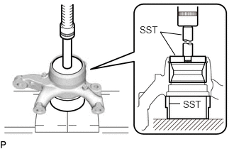
Using SST and a press, press a new front inner axle hub bearing LH (outer race) into the steering knuckle LH.
- SST
- 09527-17011
09950-60020 (09951-00750)
09950-70010 (09951-07100)
43512E
2.INSTALL FRONT AXLE HUB HOLE SNAP RING LH
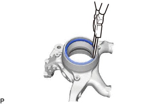
Using a snap ring pliers, install a new front axle hub hole snap ring LH to the steering knuckle LH.
43502F
3.INSTALL FRONT AXLE HUB OIL SEAL LH
Install a new front inner axle hub bearing LH (outer side inner bearing) to the steering knuckle LH.
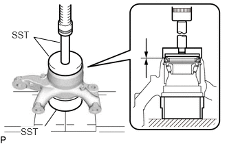
Using SST and a press, press a new front axle hub oil seal LH into the steering knuckle LH.
- SST
- 09527-17011
09950-60020 (09951-00810)
09950-70010 (09951-07100)
Apply MP grease to the lip of the front axle hub oil seal LH.
Install the dust cover with the 3 bolts.
- Torque:
- 8.0 N*m (82 kgf*cm, 71 in.*lbf)
43502C
4.INSTALL FRONT AXLE HUB SUB-ASSEMBLY LH
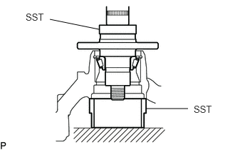
Using SST and a press, press the front axle hub sub-assembly LH into the steering knuckle LH.
- SST
- 09950-60010 (09951-00600)
09527-17011
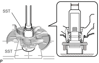
Using SST and a press, press a new front inner axle hub bearing LH (inner side inner race) into the front axle hub sub-assembly LH.
- SST
- 09223-00010
09527-17011
Install 3 new front axle hub bolts.
Click hereDrivetrain>AXLE AND DIFFERENTIAL>FRONT AXLE HUB BOLT>REPLACEMENT
43524C
5.INSTALL FRONT INNER WHEEL BEARING SPACER LH (w/o ABS)
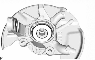
Install the front inner wheel bearing spacer LH.
43515
6.INSTALL FRONT SKID CONTROL ROTOR (w/ ABS)
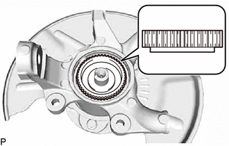
Install the front skid control rotor as shown in the illustration.
- NOTICE:
-
Take care not to scratch the serration of the front skid control rotor.
43502H
7.INSTALL FRONT AXLE SHAFT NUT LH
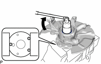
Using a 36 mm socket wrench, install a new front axle shaft nut LH to the front axle hub sub-assembly LH.
- Torque:
- 199 N*m (2029 kgf*cm, 147 ft.*lbf)
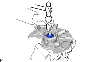
Using a chisel and hammer, stake the front axle shaft nut LH.
- NOTICE:
-
Do not scratch the serration of the front skid control rotor.
43442B
8.INSTALL KNUCKLE GREASE RETAINER CAP LH
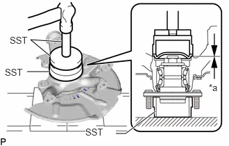
| *a | Clearance |
Using SST and a hammer, tap the knuckle grease retainer cap LH.
- SST
- 09527-17011
09950-60020 (09951-00910)
09950-70010 (09951-07150)
- Standard clearance:
0.2 mm (0.0079 in.) or less
- NOTICE:
-
Do not damage the knuckle grease retainer cap LH.
48630
9.CONNECT FRONT UPPER SUSPENSION ARM ASSEMBLY LH
Connect the front upper suspension arm assembly LH to the steering knuckle LH with a new nut.
- Torque:
- 110 N*m (1122 kgf*cm, 81 ft.*lbf)
Install a new clip.
- NOTICE:
-
If the holes for the clip are not aligned, tighten the nut an additional 60°.
48069
10.CONNECT FRONT LOWER NO. 1 SUSPENSION ARM ASSEMBLY LH
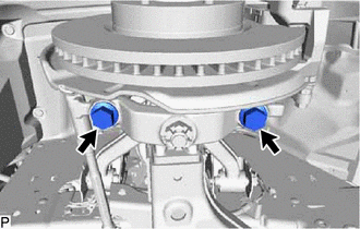
Connect the front lower No. 1 suspension arm LH to the steering knuckle LH with the 2 bolts.
- Torque:
- 160 N*m (1632 kgf*cm, 118 ft.*lbf)
45047
11.CONNECT TIE ROD END SUB-ASSEMBLY LH
43512
12.INSTALL FRONT DISC
47722
13.INSTALL FRONT DISC BRAKE CYLINDER MOUNTING LH
47750
14.INSTALL FRONT DISC BRAKE CYLINDER ASSEMBLY LH
15.CONNECT FRONT FLEXIBLE HOSE
89543
16.CONNECT FRONT SPEED SENSOR LH (w/ ABS)
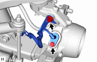
Install the front speed sensor LH with the bolt.
- Torque:
- 8.5 N*m (87 kgf*cm, 75 in.*lbf)
- NOTICE:
- ·
Make sure there are no pieces of iron or other foreign matter attached to the front speed sensor LH tip.
·While inserting the front speed sensor LH into the knuckle hole, do not strike or damage the sensor tip.
·After installing the front speed sensor LH, make sure there is no clearance or foreign matter between the sensor stay part and the knuckle.
·When installing the front speed sensor LH, do not twist the wire harness.
Install the harness clamp to the steering knuckle with the bolt.
- Torque:
- 32 N*m (326 kgf*cm, 24 ft.*lbf)
- NOTICE:
- ·
When installing the harness clamp, do not twist the wire harness.
·Make sure the clamp rotation stopper touches the installation position.
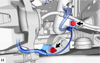
Install the harness clamp to the front lower arm bracket with the bolt.
- Torque:
- 32 N*m (326 kgf*cm, 24 ft.*lbf)
- NOTICE:
- ·
When installing the harness clamp, do not twist the wire harness.
·Make sure the harness clamp rotation stopper touches the installation position.
Install the harness clamp to the front absorber bracket with the bolt.
- Torque:
- 32 N*m (326 kgf*cm, 24 ft.*lbf)
- NOTICE:
- ·
When installing the harness clamp, do not twist the wire harness.
·Make sure the harness clamp rotation stopper touches the installation position.
17.INSTALL FRONT WHEEL
18.INSPECT AND ADJUST FRONT WHEEL ALIGNMENT
19.CHECK ABS SPEED SENSOR SIGNAL (w/ ABS)