2GD-FTV EMISSION CONTROL UREA PUMP INSTALLATION
PROCEDURE

 77871A
1.INSTALL UREA PUMP
Install a new gasket to the urea tank sub-assembly.
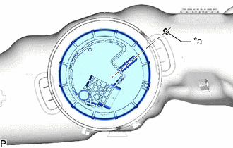
| *a | Matchmark |
Install the urea pump to the urea tank sub-assembly as shown in the illustration.
Put the urea pump gauge retainer to the urea tank sub-assembly. While holding the urea pump, tighten the urea pump gauge retainer one complete turn by hand.
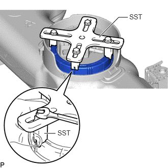
Set SST on the urea pump gauge retainer.
- SST
- 09808-14030 (09808-01030, 09808-01040)
- HINT:
- ·
Attach the claws of SST securely with the urea pump gauge retainer holes to secure SST.
·Install SST while pressing the claws of SST against the urea pump gauge retainer (towards the center of SST).
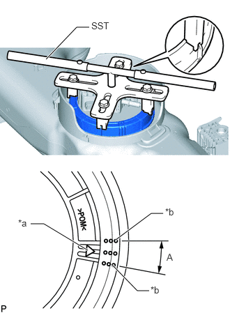
| *a | Urea Pump Gauge Retainer Side Mark |
| *b | Urea Tank Sub-assembly Side Mark |
Using SST, tighten the urea pump gauge retainer until it is within range A on the urea tank sub-assembly as shown in the illustration.
- SST
- 09808-14030 (09808-01010)
- NOTICE:
-
Remove any foreign matter around the urea pump before this operation.
- HINT:
-
Fit the tips of SST onto the ribs of the urea pump gauge retainer.
2.INSTALL NO. 1 UREA TUBE WITH HEATER
- NOTICE:
-
Check for dirt or mud on the urea pump and around the urea tube connector before connection. Clean if necessary.
Install the No. 1 urea tube with heater to the urea pump.
- HINT:
-
If there is any solidified urea solution (white solids) on the connection areas of the No. 1 urea tube with heater and urea pump, clean the solids off with water. Otherwise, they may prevent the O-ring from sealing properly.
Wash the connection area of the urea tube connector with water to remove all solidified urea solution (white solids).
Wipe off the connection area of the urea pump with water to remove all solidified urea solution (white solids).
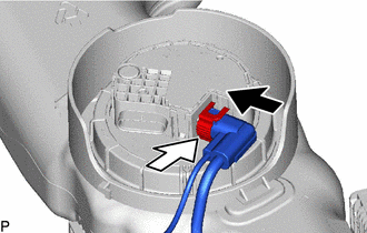

|
Push |

|
Push Down |
Align the axis of the urea tube connector with the axis of the urea pump. Push the urea tube connector into the urea pump until the urea tube connector makes a "click" sound.
After connecting the urea pump and the urea tube connector, check that the urea pump and urea tube connector are securely connected by trying to pull them apart.
Attach the lock claws to the urea tube connector by pushing down on the cover.
Attach the 2 clamps and connect the No. 1 urea tube with heater to the urea tank sub-assembly.
3.INSTALL UREA TANK HARNESS
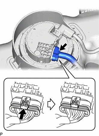
Connect the connector to the urea pump as shown in the illustration.
Attach the clamp and connect the connector to the No. 1 urea tube with heater.
77801A
4.INSTALL UREA TANK SUB-ASSEMBLY