STEERING COLUMN STEERING COLUMN ASSEMBLY REMOVAL
CAUTION / NOTICE / HINT
The necessary procedures (adjustment, calibration, initialization or registration) that must be performed after parts are removed, installed or replaced during the steering column assembly removal/installation are shown below.
| Replacement Part or Procedure | Necessary Procedures | Effects / Inoperative when not Performed | Link |
|---|---|---|---|
| Disconnect cable from negative battery terminal | Drive the vehicle until stop and start control is permitted (approximately 5 to 40 minutes) | Stop and start system | ( ) |
- CAUTION:
-
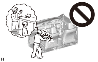
-
Some of these service operations affect the SRS. Read the precautionary notices concerning the SRS before servicing.
-
for Type A : Click hereVehicle Interior>SUPPLEMENTAL RESTRAINT SYSTEMS>AIRBAG SYSTEM(for Type A)>PRECAUTION
-
for Type B : Click hereVehicle Interior>SUPPLEMENTAL RESTRAINT SYSTEMS>AIRBAG SYSTEM(for Type B)>PRECAUTION
-
for Type C : Click hereVehicle Interior>SUPPLEMENTAL RESTRAINT SYSTEMS>AIRBAG SYSTEM(for Type C)>PRECAUTION
CAUTION / NOTICE / HINT
- HINT:
- ·
Use the same procedure for RHD and LHD vehicles.
·The procedure listed below is for LHD vehicles.
PROCEDURE

 1.PLACE FRONT WHEELS FACING STRAIGHT AHEAD
2.DISCONNECT CABLE FROM NEGATIVE BATTERY TERMINAL
- CAUTION:
-
Wait at least 90 seconds after disconnecting the cable from the negative (-) battery terminal to disable the SRS system.
- NOTICE:
-
When disconnecting the cable, some systems need to be initialized after the cable is reconnected.
-
Click hereGeneral>INTRODUCTION>REPAIR INSTRUCTION>INITIALIZATION
45100
3.REMOVE STEERING WHEEL ASSEMBLY
45287
4.REMOVE STEERING COLUMN LOWER COVER
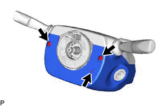
Remove the 3 bolts.
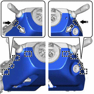

|
Place Hands Here |

|
Remove in this Direction (1) |

|
Remove in this Direction (2) |
Detach the 2 claws and 6 guides to remove the steering column lower cover.
45286B
5.REMOVE STEERING COLUMN UPPER COVER
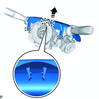
|
|
Remove in this Direction |
Detach the 2 claws and 2 guides to remove the steering column upper cover.
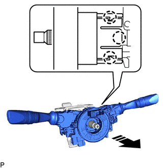
6.REMOVE COMBINATION SWITCH ASSEMBLY WITH SPIRAL CABLE SUB-ASSEMBLY
Disconnect the connectors from the combination switch assembly with spiral cable sub-assembly.
|
|
Remove in this Direction |
Detach the 3 claws. Remove the combination switch assembly with spiral cable sub-assembly from the steering column sub-assembly.
73900
7.REMOVE NO. 1 INSTRUMENT LOWER PANEL AIRBAG ASSEMBLY
45219
8.DISCONNECT STEERING SLIDING YOKE
45025D
9.REMOVE NO. 1 STEERING COLUMN HOLE COVER SUB-ASSEMBLY
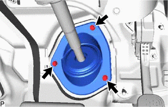
Remove the 3 bolts and No. 1 steering column hole cover sub-assembly.
45250
10.REMOVE STEERING COLUMN ASSEMBLY
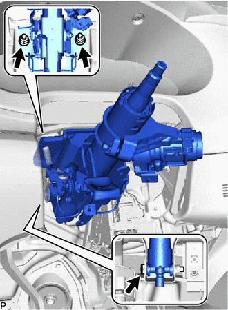
Remove the bolt and 2 nuts, and then pull out the steering column assembly together with the steering sliding with coupling yoke.