2GD-FTV STARTING STARTER(w/ Stop And Start System) INSTALLATION
PROCEDURE

 28100
1.INSTALL STARTER ASSEMBLY
for Automatic Transmission:
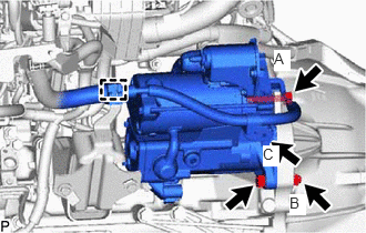
Temporarily install the starter assembly and connect the ground cable with the nut and 3 bolts.
Attach the clamp.
Tighten bolt A and nut B.
- Torque:
- 68 N*m (693 kgf*cm, 50 ft.*lbf)
Tighten bolt C.
- Torque:
- 12.6 N*m (128 kgf*cm, 9 ft.*lbf)
for Manual Transmission:
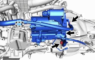
Temporarily install the starter assembly, No. 1 clutch tube bracket and connect the ground cable with the 3 bolts.
Attach the clamp.
Tighten bolt A and bolt B.
- Torque:
- 68 N*m (693 kgf*cm, 50 ft.*lbf)
Tighten bolt C.
- Torque:
- 12.6 N*m (128 kgf*cm, 9 ft.*lbf)
Install the starter wire with the nut.
- Torque:
- 21.1 N*m (215 kgf*cm, 16 ft.*lbf)
Connect the 2 starter connectors.
77827A
2.INSTALL NO. 2 UREA TANK FILLER PIPE SUPPORT (w/ Urea SCR System)
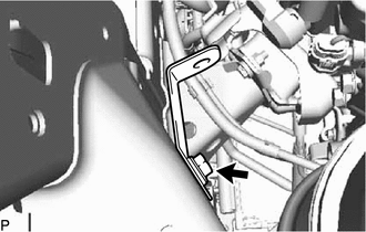
Install the No. 2 urea tank filler pipe support to the frame with the bolt.
- Torque:
- 14.3 N*m (146 kgf*cm, 11 ft.*lbf)
77801A
3.INSTALL UREA TANK SUB-ASSEMBLY (w/ Urea SCR System)
4.CONNECT CLUTCH RELEASE CYLINDER ASSEMBLY (for Manual Transmission)
31485
5.INSTALL CLUTCH FLEXIBLE HOSE BRACKET (for Manual Transmission)
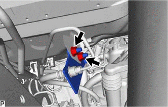
Install the clutch flexible hose bracket with the 2 nuts.
- Torque:
- 15 N*m (153 kgf*cm, 11 ft.*lbf)
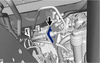
Install a new clip to the clutch flexible hose bracket.
41110F
6.CONNECT FRONT DIFFERENTIAL CARRIER ASSEMBLY (for 4WD)
Install the 2 upper differential mount stoppers to the front differential carrier assembly.
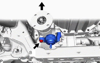
Lift up the front differential carrier assembly and temporarily install the No. 3 differential support with bolt B.
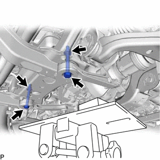
Temporarily install the 2 front mounting bolts, 2 nuts and 2 lower differential mount stoppers.
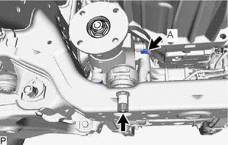
Lower the transmission jack a little at a time and temporarily install the front differential carrier assembly with bolt A and the differential mount nut.
Remove the transmission jack.
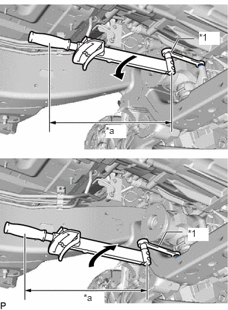
| *1 | 17 mm Ball Joint Lock Nut Wrench |
| *a | Fulcrum Length |
Using a 17 mm ball joint lock nut wrench, tighten the 2 bolts.
- Torque:
- Specified tightening torque : 107.9 N*m (1100 kgf*cm, 80 ft.*lbf)
- HINT:
- ·
Calculate the torque wrench reading when changing the fulcrum length of the torque wrench.
Click hereGeneral>INTRODUCTION>REPAIR INSTRUCTION>PRECAUTION
·When using a ball joint lock nut wrench (fulcrum length of 149 mm (5.87 in.)) + torque wrench (fulcrum length of 380 mm (15.0 in.)): 77.5 N*m (790 kgf*cm, 57 ft.*lbf)
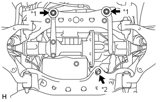
| *1 | Front Mounting Bolt |
| *2 | Differential Mounting Nut |
Tighten the 2 front mounting bolts.
- Torque:
- 105 N*m (1071 kgf*cm, 77 ft.*lbf)
Using a 12 mm hexagon socket wrench, tighten the differential mount nut.
- Torque:
- 93.5 N*m (953 kgf*cm, 69 ft.*lbf)
Install the bracket with the bolt.
- Torque:
- 18.6 N*m (190 kgf*cm, 14 ft.*lbf)
Connect the differential oil temperature sensor connector.
Install the bracket with the bolt.
- Torque:
- 18.6 N*m (190 kgf*cm, 14 ft.*lbf)
Connect the differential motor actuator connector.
Connect the hose to the front differential union.
Connect the hose to the differential motor actuator assembly.
Install the front differential breather tube bracket with the bolt.
- Torque:
- 12.7 N*m (130 kgf*cm, 9 ft.*lbf)
37140
7.INSTALL FRONT PROPELLER SHAFT ASSEMBLY (for 4WD)
53882K
8.INSTALL FRONT FENDER SEAL LH
Install the front fender seal LH with 6 new clips.
51442
9.INSTALL NO. 2 ENGINE UNDER COVER
51410
10.INSTALL NO. 1 ENGINE UNDER COVER ASSEMBLY
11.CONNECT CABLE TO NEGATIVE BATTERY TERMINAL
- NOTICE:
-
When disconnecting the cable, some systems need to be initialized after the cable is reconnected.
-
Click hereGeneral>INTRODUCTION>REPAIR INSTRUCTION>INITIALIZATION