PRE-CRASH SAFETY PRE-CRASH SAFETY SYSTEM C1A4B Stop Light Relay Circuit
DESCRIPTION
The skid control ECU (brake actuator assembly) sends a stop light operation request signal to the stop light control relay (STOP/CDS FAN Relay). If the skid control ECU (brake actuator assembly) detects a malfunction in the stop light control relay (STOP/CDS FAN Relay) circuit, the millimeter wave radar sensor assembly stores DTC C1A4B.
| DTC No. | Detection Item | DTC Detection Condition | Trouble Area |
|---|---|---|---|
| C1A4B | Stop Light Relay Circuit | Diagnosis condition:
·
Ignition switch to ON and battery voltage between 11 and 14 V Malfunction condition: Either of the following conditions is met: ·
When the stop light illumination output (STPO) signal is on, a signal has not been input to the STP terminal for 0.3 seconds or more continuously. ·
When the stop light illumination output (STPO) signal is off, signals input to the STP terminal and STP2 terminal of the skid control ECU (brake actuator assembly) differ for 0.3 seconds or more continuously. |
·
Vehicle stability control system ·
Millimeter wave radar sensor assembly ·
Skid control ECU (Brake actuator assembly) |
WIRING DIAGRAM
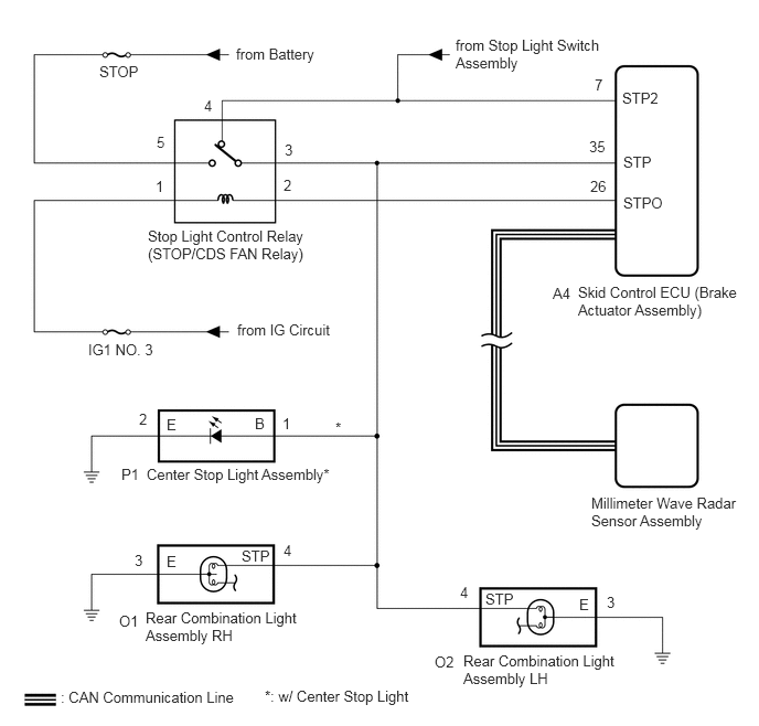
CAUTION / NOTICE / HINT
- NOTICE:
-
The pre-crash safety system uses the CAN communication system. First, confirm that there are no malfunction in the CAN communication system. Refer to How to Proceed with Troubleshooting.
-
for LHD: Click herePower Source / Network>NETWORKING>CAN COMMUNICATION SYSTEM(for LHD with Central Gateway ECU)>HOW TO PROCEED WITH TROUBLESHOOTING
-
for RHD: Click herePower Source / Network>NETWORKING>CAN COMMUNICATION SYSTEM(for RHD with Central Gateway ECU)>HOW TO PROCEED WITH TROUBLESHOOTING
PROCEDURE
- HINT:
-
Pre-crash safety system DTC C1A4B may be stored due to a malfunction in the VSC system. Therefore, it is necessary to check for and troubleshoot VSC system DTCs first.
Check for DTCs.
Click hereBrake>BRAKE CONTROL / DYNAMIC CONTROL SYSTEMS>VEHICLE STABILITY CONTROL SYSTEM>DTC CHECK / CLEAR
- Chassis > ABS/VSC/TRC > Trouble Codes
- 50001 105
- Result:
Result Proceed to Vehicle stability control system DTCs are not output A Vehicle stability control system DTCs are output B
A
B
Clear the DTCs.
Click hereVehicle Interior>PRE-CRASH SAFETY>PRE-CRASH SAFETY SYSTEM>DTC CHECK / CLEAR
- Body Electrical > Pre-Crash 2 > Clear DTCs
- 50002 220
Make sure that the DTC detection conditions are met.
- HINT:
-
If the detection conditions are not met, the system cannot detect the malfunction.
Check for DTCs.
Click hereVehicle Interior>PRE-CRASH SAFETY>PRE-CRASH SAFETY SYSTEM>DTC CHECK / CLEAR
- Body Electrical > Pre-Crash 2 > Trouble Codes
- 50001 220
- Result:
Result Proceed to DTC C1A4B is output A DTC C1A4B is not output B
A
B
Click hereGeneral>INTRODUCTION>HOW TO TROUBLESHOOT ECU CONTROLLED SYSTEMS>HOW TO PROCEED WITH TROUBLESHOOTING
Replace the millimeter wave radar sensor assembly.
Click hereEngine / Hybrid System>CRUISE CONTROL>MILLIMETER WAVE RADAR SENSOR>REMOVAL
Adjust the millimeter wave radar sensor assembly.
Click hereEngine / Hybrid System>CRUISE CONTROL>MILLIMETER WAVE RADAR SENSOR>ADJUSTMENT
- Result:
Proceed to NEXT
NEXT
- HINT:
-
After performing the radar sensor beam axis adjustment, if the same DTC is output again after the DTC detection conditions are met, replace the millimeter wave radar sensor assembly.
Clear the DTCs.
Click hereVehicle Interior>PRE-CRASH SAFETY>PRE-CRASH SAFETY SYSTEM>DTC CHECK / CLEAR
- Body Electrical > Pre-Crash 2 > Clear DTCs
- 50002 220
Make sure that the DTC detection conditions are met.
- HINT:
-
If the detection conditions are not met, the system cannot detect the malfunction.
Check for DTCs.
Click hereVehicle Interior>PRE-CRASH SAFETY>PRE-CRASH SAFETY SYSTEM>DTC CHECK / CLEAR
- Body Electrical > Pre-Crash 2 > Trouble Codes
- 50001 220
- Result:
Result Proceed to DTC C1A4B is not output A DTC C1A4B is output B
A
B