2GD-FTV ENGINE CONTROL RELAY(w/ Urea SCR System) ON-VEHICLE INSPECTION
CAUTION / NOTICE / HINT
The necessary procedures (adjustment, calibration, initialization, or registration) that must be performed after parts are removed, installed, or replaced during the body ECU removal/installation are shown below.
| Replacement Part or Procedure | Necessary Procedures | Effects/Inoperative when not Performed | Link |
|---|---|---|---|
| Replacement of body ECU | Initialize automatic light control system | Automatic light control system | ( ) |
PROCEDURE

 1.INSPECT EDU RELAY (EDU)
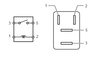
Measure the resistance according to the value(s) in the table below.
- Standard Resistance:
Tester Connection Condition Specified Condition 3 - 5 Battery voltage not applied to terminals 1 and 2 10 kΩ or higher Battery voltage applied to terminals 1 and 2 Below 1 Ω
If the result is not as specified, replace the EDU relay.
2.INSPECT IG2 RELAY (IG2)
Measure the resistance according to the value(s) in the table below.
- Standard Resistance:
Tester Connection Condition Specified Condition 3 - 5 Battery voltage not applied to terminals 1 and 2 10 kΩ or higher Battery voltage applied to terminals 1 and 2 Below 1 Ω
If the result is not as specified, replace the IG2 relay.
3.INSPECT NOX PM RELAY (NOX PM)
Measure the resistance according to the value(s) in the table below.
- Standard Resistance:
Tester Connection Condition Specified Condition 3 - 5 Battery voltage not applied to terminals 1 and 2 10 kΩ or higher Battery voltage applied to terminals 1 and 2 Below 1 Ω
If the result is not as specified, replace the NOX PM relay.
4.INSPECT DCU RELAY (DCU)
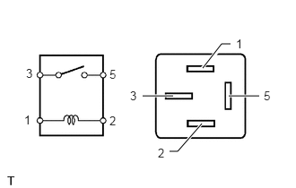
Measure the resistance according to the value(s) in the table below.
- Standard Resistance:
Tester Connection Condition Specified Condition 3 - 5 Battery voltage not applied to terminals 1 and 2 10 kΩ or higher Battery voltage applied to terminals 1 and 2 Below 1 Ω
If the result is not as specified, replace the DCU relay.
82730
5.INSPECT INSTRUMENT PANEL JUNCTION BLOCK ASSEMBLY
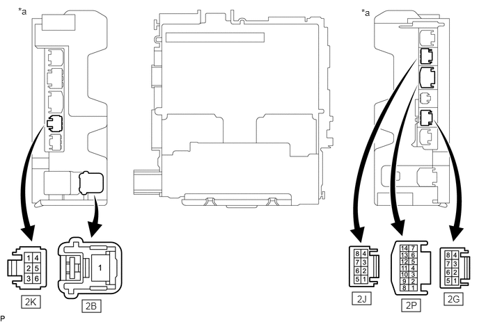
| *a | Component without harness connected
(Instrument Panel Junction Block Assembly) |
- | - |
- NOTICE:
-
Before performing the relay inspections for the relays of the instrument panel junction block assembly, inspect the EFI-MAIN NO. 1, EFI-MAIN NO. 2 and EFI NO. 1 fuses.
Remove the instrument panel junction block assembly.
for LHD:
Click herePower Source / Network>POWER DISTRIBUTION>MAIN BODY ECU(for LHD)>REMOVAL
for RHD:
Click herePower Source / Network>POWER DISTRIBUTION>MAIN BODY ECU(for RHD)>REMOVAL
Remove the body ECU from the instrument panel junction block assembly.
for LHD:
Click herePower Source / Network>POWER DISTRIBUTION>MAIN BODY ECU(for LHD)>REMOVAL
for RHD:
Click herePower Source / Network>POWER DISTRIBUTION>MAIN BODY ECU(for RHD)>REMOVAL
Inspect the EFI-MAIN NO. 1 relay.
Measure the resistance according to the value(s) in the table below.
- Standard Resistance:
Tester Connection Condition Specified Condition 2B-1 - 2G-5 Battery voltage not applied to terminals 2P-8 and 2K-3 10 kΩ or higher Battery voltage applied to terminals 2P-8 and 2K-3 Below 1 Ω
If the result is not as specified, replace the instrument panel junction block assembly.
Inspect the EFI-MAIN NO. 2 relay.
Measure the resistance according to the value(s) in the table below.
- Standard Resistance:
Tester Connection Condition Specified Condition 2B-1 - 2G-3 Battery voltage not applied to terminals 2P-9 and 2J-5 10 kΩ or higher Battery voltage applied to terminals 2P-9 and 2J-5 Below 1 Ω
If the result is not as specified, replace the instrument panel junction block assembly.
Install the body ECU to the instrument panel junction block assembly.
Install the instrument panel junction block assembly.