SUPPLEMENTAL RESTRAINT SYSTEMS AIRBAG SYSTEM(for Type C) B1925/78 Short in Rear Pretensioner Squib LH Circuit B1926/78 Open in Rear Pretensioner Squib LH Circuit B1927/78 Short to GND in Rear Pretensioner Squib LH Circuit B1928/78 Short to B+ in Rear Pretensioner Squib LH Circuit
DESCRIPTION
The rear pretensioner LH circuit consists of the airbag sensor assembly and rear No. 1 seat outer belt assembly LH.
This circuit instructs the SRS to deploy when deployment conditions are met.
These DTCs are stored when a malfunction is detected in the rear pretensioner LH circuit.
| DTC No. | Detection Item | DTC Detection Condition | Trouble Area |
|---|---|---|---|
| B1925/78 | Short in Rear Pretensioner Squib LH Circuit | One of the following conditions is met:
·
The airbag sensor assembly detects a line short circuit signal 5 times in the rear pretensioner LH circuit during the primary check. ·
A rear No. 1 seat outer belt assembly LH malfunction. ·
An airbag sensor assembly malfunction. |
·
No. 2 floor wire ·
Rear No. 1 seat outer belt assembly LH ·
Airbag sensor assembly |
| B1926/78 | Open in Rear Pretensioner Squib LH Circuit | One of the following conditions is met:
·
The airbag sensor assembly detects an open circuit signal in the rear pretensioner LH circuit for 2 seconds. ·
A rear No. 1 seat outer belt assembly LH malfunction. ·
An airbag sensor assembly malfunction. |
·
No. 2 floor wire ·
Rear No. 1 seat outer belt assembly LH ·
Airbag sensor assembly |
| B1927/78 | Short to GND in Rear Pretensioner Squib LH Circuit | One of the following conditions is met:
·
The airbag sensor assembly detects a short circuit to ground signal in the rear pretensioner LH circuit for 0.5 seconds. ·
A rear No. 1 seat outer belt assembly LH malfunction. ·
An airbag sensor assembly malfunction. |
·
No. 2 floor wire ·
Rear No. 1 seat outer belt assembly LH ·
Airbag sensor assembly |
| B1928/78 | Short to B+ in Rear Pretensioner Squib LH Circuit | One of the following conditions is met:
·
The airbag sensor assembly detects a short circuit to B+ signal in the rear pretensioner LH circuit for 0.5 seconds. ·
A rear No. 1 seat outer belt assembly LH malfunction. ·
An airbag sensor assembly malfunction. |
·
No. 2 floor wire ·
Rear No. 1 seat outer belt assembly LH ·
Airbag sensor assembly |
WIRING DIAGRAM
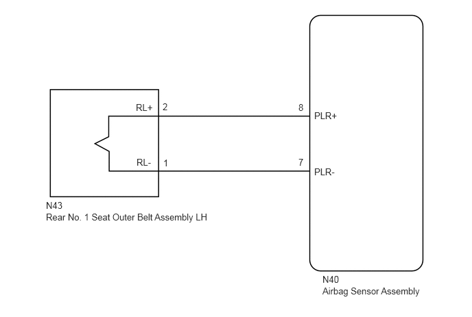
CAUTION / NOTICE / HINT
- NOTICE:
- ·
After turning the ignition switch off, waiting time may be required before disconnecting the cable from the negative (-) battery terminal. Therefore, make sure to read the disconnecting the cable from the negative (-) battery terminal notices before proceeding with work.
Click hereGeneral>INTRODUCTION>REPAIR INSTRUCTION>PRECAUTION
·When disconnecting the cable from the negative (-) battery terminal while performing repairs, some systems need to be initialized after the cable is reconnected.
Click hereGeneral>INTRODUCTION>REPAIR INSTRUCTION>INITIALIZATION
·After replacing the airbag sensor assembly, refer to initialization.
Click hereGeneral>INTRODUCTION>REPAIR INSTRUCTION>INITIALIZATION
- HINT:
-
To perform the simulation method, enter check mode (signal check) with the GTS (Click here Vehicle Interior>SUPPLEMENTAL RESTRAINT SYSTEMS>AIRBAG SYSTEM(for Type C)>CHECK MODE PROCEDURE), and then wiggle each connector of the airbag system or drive the vehicle on various types of road (Click here Vehicle Interior>SUPPLEMENTAL RESTRAINT SYSTEMS>AIRBAG SYSTEM(for Type C)>DIAGNOSIS SYSTEM).
PROCEDURE
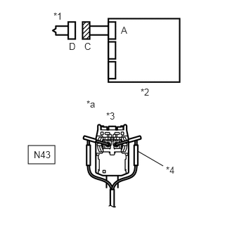
| *1 | Rear No. 1 Seat Outer Belt Assembly LH |
| *2 | Airbag Sensor Assembly |
| *3 | Connector C |
| *4 | SST |
| *a | Front view of wire harness connector
(to Rear No. 1 Seat Outer Belt Assembly LH) |
Turn the ignition switch off.
Disconnect the cable from the negative (-) battery terminal, and wait for at least 90 seconds.
Disconnect the connector from the rear No. 1 seat outer belt assembly LH.
Connect the white wire side of SST (resistance: 2.1 Ω) to connector C.
- CAUTION:
-
Never connect the tester to the rear No. 1 seat outer belt assembly LH for measurement, as this may lead to a serious injury due to airbag deployment.
- NOTICE:
- ·
Do not forcibly insert SST into the terminals of the connector when connecting SST.
·Insert SST straight into the terminals of the connector.
- SST
- 09843-18061
Connect the cable to the negative (-) battery terminal, and wait for at least 2 seconds.
Turn the ignition switch to ON, and wait for at least 60 seconds.
Clear the DTCs.
Click hereVehicle Interior>SUPPLEMENTAL RESTRAINT SYSTEMS>AIRBAG SYSTEM(for Type C)>DTC CHECK / CLEAR
- Body Electrical > SRS Airbag > Clear DTCs
- 50002 188
Turn the ignition switch off.
Turn the ignition switch to ON, and wait for at least 60 seconds.
Check for DTCs.
Click hereVehicle Interior>SUPPLEMENTAL RESTRAINT SYSTEMS>AIRBAG SYSTEM(for Type C)>DTC CHECK / CLEAR
- Body Electrical > SRS Airbag > Trouble Codes
- 50001 188
- Result:
Proceed to DTC B1925/78, B1926/78, B1927/78 or B1928/78 is not output DTC B1925/78, B1926/78, B1927/78 or B1928/78 is output
- HINT:
-
Codes other than DTC B1925/78, B1926/78, B1927/78 or B1928/78 may be output at this time, but they are not related to this check.
Turn the ignition switch off.
Disconnect the cable from the negative (-) battery terminal, and wait for at least 90 seconds.
Disconnect SST from connector C.
DTC B1925/78, B1926/78, B1927/78 or B1928/78 is not output
for Double Cab: Click hereVehicle Interior>SEAT BELT>REAR SEAT OUTER BELT ASSEMBLY(for Double Cab)>REMOVAL
for Smart Cab: Click hereVehicle Interior>SEAT BELT>REAR SEAT OUTER BELT ASSEMBLY(for Smart Cab)>REMOVAL
DTC B1925/78, B1926/78, B1927/78 or B1928/78 is output
Disconnect the connectors from the airbag sensor assembly.
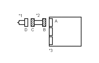
| *1 | Rear No. 1 Seat Outer Belt Assembly LH |
| *2 | No. 2 Floor Wire |
| *3 | Airbag Sensor Assembly |
Check that the connectors (on the airbag sensor assembly side and rear No. 1 seat outer belt assembly LH side) are not damaged.
- OK:
The lock button is not disengaged, and the claw of the lock is not deformed or damaged.
- Result:
Proceed to OK NG
OK
NG
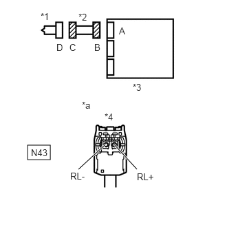
| *1 | Rear No. 1 Seat Outer Belt Assembly LH |
| *2 | No. 2 Floor Wire |
| *3 | Airbag Sensor Assembly |
| *5 | Connector C |
| *a | Front view of wire harness connector
(to Rear No. 1 Seat Outer Belt Assembly LH) |
Connect the cable to the negative (-) battery terminal, and wait for at least 2 seconds.
Turn the ignition switch to ON.
Measure the voltage according to the value(s) in the table below.
- Standard Voltage:
Tester Connection Switch Condition Specified Condition N43-1 (RL-) - Body ground Ignition switch ON Below 1 V N43-2 (RL+) - Body ground Ignition switch ON Below 1 V
Turn the ignition switch off.
Disconnect the cable from the negative (-) battery terminal, and wait for at least 90 seconds.
Measure the resistance according to the value(s) in the table below.
- Standard Resistance:
Tester Connection Condition Specified Condition N43-1 (RL-) - N43-2 (RL+) Always Below 1 Ω
Release the activation prevention mechanism built into connector B.
Click hereVehicle Interior>SUPPLEMENTAL RESTRAINT SYSTEMS>AIRBAG SYSTEM(for Type C)>DIAGNOSIS SYSTEM
Measure the resistance according to the value(s) in the table below.
- Standard Resistance:
Tester Connection Condition Specified Condition N43-1 (RL-) - N43-2 (RL+) Always 1 MΩ or higher
Restore the released activation prevention mechanism of connector B to its original condition.
Measure the resistance according to the value(s) in the table below.
- Standard Resistance:
Tester Connection Condition Specified Condition N43-1 (RL-) - Body ground Always 1 MΩ or higher N43-2 (RL+) - Body ground Always 1 MΩ or higher
- Result:
Proceed to OK NG
OK
NG
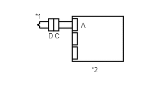
| *1 | Rear No. 1 Seat Outer Belt Assembly LH |
| *2 | Airbag Sensor Assembly |
Connect the connectors to the rear No. 1 seat outer belt assembly LH and airbag sensor assembly.
Connect the cable to the negative (-) battery terminal, and wait for at least 2 seconds.
Turn the ignition switch to ON, and wait for at least 60 seconds.
Clear the DTCs.
Click hereVehicle Interior>SUPPLEMENTAL RESTRAINT SYSTEMS>AIRBAG SYSTEM(for Type C)>DTC CHECK / CLEAR
- Body Electrical > SRS Airbag > Clear DTCs
- 50002 188
Turn the ignition switch off.
Turn the ignition switch to ON, and wait for at least 60 seconds.
Check for DTCs.
Click hereVehicle Interior>SUPPLEMENTAL RESTRAINT SYSTEMS>AIRBAG SYSTEM(for Type C)>DTC CHECK / CLEAR
- Body Electrical > SRS Airbag > Trouble Codes
- 50001 188
- Result:
Proceed to DTC B1925/78, B1926/78, B1927/78 or B1928/78 is not output DTC B1925/78, B1926/78, B1927/78 or B1928/78 is output
- HINT:
-
Codes other than DTC B1925/78, B1926/78, B1927/78 and B1928/78 may be output at this time, but they are not related to this check.
DTC B1925/78, B1926/78, B1927/78 or B1928/78 is not output
Click hereVehicle Interior>SUPPLEMENTAL RESTRAINT SYSTEMS>AIRBAG SYSTEM(for Type C)>DIAGNOSIS SYSTEM
DTC B1925/78, B1926/78, B1927/78 or B1928/78 is output