2GD-FTV EMISSION CONTROL EGR VALVE(w/o EGR Cooler) INSTALLATION
PROCEDURE

 25800
1.INSTALL ELECTRIC EGR CONTROL VALVE ASSEMBLY
Install a new gasket and the electric EGR control valve assembly to the EGR valve adapter sub-assembly with the 2 bolts.
- Torque:
- 25 N*m (255 kgf*cm, 18 ft.*lbf)
Connect the No. 9 water by-pass hose to the electric EGR control valve assembly, and slide the clamp to secure the hose.
Attach the clamp and connect the connector to the common rail assembly.
25612
2.INSTALL NO. 2 EGR PIPE
Install 2 new gaskets and No. 2 EGR pipe to the electric EGR control valve assembly and the intake manifold with the 4 nuts.
- Torque:
- 29 N*m (296 kgf*cm, 21 ft.*lbf)
25625
3.INSTALL EGR VALVE BRACKET
Install the EGR valve bracket to the electric EGR control valve assembly and intake manifold with the bolt and nut.
- Torque:
- 21 N*m (214 kgf*cm, 15 ft.*lbf)
82121
4.CONNECT ENGINE WIRE
Attach the clamp and install the bolt.
- Torque:
- 18.5 N*m (189 kgf*cm, 14 ft.*lbf)
Attach the clamp and connect the connector to the power steering oil pressure switch.
Attach the clamp and install the bolt.
- Torque:
- 12.5 N*m (127 kgf*cm, 9 ft.*lbf)
Connect the connector to the sensor wire of the common rail assembly.
Connect the connector to the glow plug connector.
Connect the connector to the electric EGR control valve assembly.
Connect the 4 connectors to the 4 injector assemblies.
Connect the connector to the camshaft position sensor.
Attach the 2 clamps and connect the 2 connectors to the turbocharger sub-assembly.
23300
5.CONNECT FUEL FILTER ASSEMBLY
Connect the fuel filter assembly to the fuel filter support.
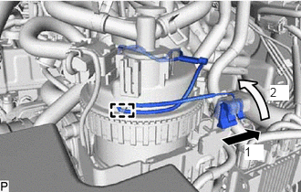
Attach the clamp and slide the lead wire as shown in the illustration to install it.
12632
6.INSTALL NO. 2 ENGINE COVER BRACKET
Install the No. 2 engine cover bracket to the No. 3 water by-pass pipe sub-assembly and EGR valve adapter sub-assembly with the 2 bolts.
- Torque:
- 10 N*m (102 kgf*cm, 7 ft.*lbf)
44763C
7.INSTALL NO. 2 HOSE TO HOSE TUBE
Install the No. 2 hose to hose tube to the cylinder head cover sub-assembly and hose bracket with the 2 bolts.
- Torque:
- 10 N*m (102 kgf*cm, 7 ft.*lbf)
Connect the union to check valve hose to the vacuum pump assembly, and slide the clamp to secure the hose.
Connect the union to connector tube hose to the No. 1 hose to hose tube, and slide the clamp to secure the hose.
89421C
8.INSTALL TURBO PRESSURE SENSOR
Install the turbo pressure sensor to the No. 3 water by-pass pipe sub-assembly with the bolt.
- Torque:
- 10 N*m (102 kgf*cm, 7 ft.*lbf)
Connect the connector to the turbo pressure sensor.
23265C
9.INSTALL GAS FILTER
Install the gas filter to the gas filter bracket.
Connect the 2 vacuum hoses to the turbo pressure sensor and intake manifold.
16278
10.INSTALL NO. 2 WATER BY-PASS PIPE
Install the No. 2 water by-pass pipe to the cylinder head cover sub-assembly, No. 3 water by-pass pipe sub-assembly and No. 2 engine cover bracket with the 4 bolts.
- Torque:
- 10 N*m (102 kgf*cm, 7 ft.*lbf)
Connect the No. 16 water by-pass hose to the EGR pipe stay, and slide the clamp to secure the hose.
Connect the 2 heater hoses to the No. 2 water by-pass pipe, and slide the 2 clamps to secure the 2 hoses.
Connect the No. 15 water by-pass hose to the water by-pass pipe, and slide the clamp to secure the hose.
Connect the No. 2 water by-pass pipe to the No. 13 water by-pass hose, and slide the clamp to secure the hose.
26100G
11.INSTALL DIESEL THROTTLE BODY ASSEMBLY
12.ADD ENGINE COOLANT
13.INSPECT FOR COOLANT LEAK