WINDOW / GLASS WINDSHIELD GLASS INSTALLATION
CAUTION / NOTICE / HINT
- HINT:
-
A bolt without a torque specification is shown in the standard bolt chart.
-
Click hereGeneral>SPECIFICATIONS>STANDARD BOLT>SPECIFIED TORQUE FOR STANDARD BOLTS
PROCEDURE

 56111
1.CLEAN WINDSHIELD GLASS
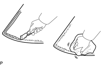
When reusing the windshield glass:
Using a scraper, remove the stoppers, adhesive dam, moulding, adhesive and double-sided tape sticking to the windshield glass.
- NOTICE:
-
Do not damage the windshield glass.
Clean the outer edges of the windshield glass with non-residue solvent.
- NOTICE:
-
Even if using a new windshield glass, clean it with non-residue solvent.
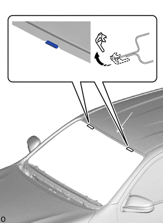

|
Remove in this Direction |
for 2-piece Type:
Remove the 2 windshield glass stoppers.
- NOTICE:
-
Make sure to replace the installed windshield glass stoppers with new ones.
56115C
2.INSTALL WINDSHIELD GLASS STOPPER
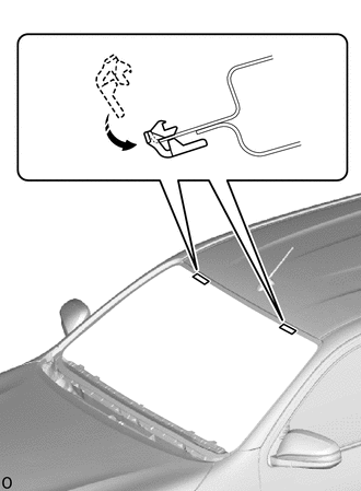

|
Install in this Direction |
Install 2 new windshield glass stoppers to the vehicle body as shown in the illustration.
- NOTICE:
-
Only 2-piece type windshield glass stoppers are supplied. Therefore, it is necessary to use the 2-piece type windshield glass stoppers even on vehicles with 1-piece type windshield glass stoppers.
56116C
3.INSTALL NO. 2 WINDSHIELD GLASS STOPPER
- HINT:
-
The supplied No. 2 windshield glass stoppers are the 2-piece type. Therefore, it is necessary to use the 2-piece type No. 2 windshield glass stoppers on vehicles with the 1-piece type windshield glass stoppers.
Apply Primer G to the No. 2 windshield glass stopper installation area on the windshield glass.
- NOTICE:
-
Do not apply too much Primer G.
Install 2 new No. 2 windshield glass stoppers to the windshield glass in the locations shown in the illustration.
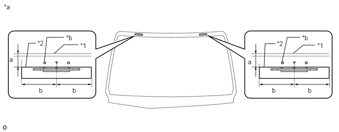
| *1 | Windshield Glass | *2 | No. 2 Windshield Glass Stopper |
| *a | Back of Windshield Glass | *b | Ceramic Notch |
- Standard:
Area Measurement a 14.8 mm (0.583 in.) b 40.0 mm (1.57 in.)
- NOTICE:
- ·
Install the No. 2 windshield glass stopper after Primer G has been allowed to dry (approximately 3 min).
·Make sure to install the No. 2 windshield glass stopper in the correct orientation.
56117A
4.INSTALL WINDOW GLASS ADHESIVE DAM
- HINT:
-
The supplied window glass adhesive dam is a 1-piece type. Therefore, it is necessary to use the 1-piece type window glass adhesive dam on vehicles with the 3-piece type window glass adhesive dam.
Apply Primer G to the windshield glass adhesive dam installation area on the windshield glass.
- NOTICE:
-
Do not apply too much Primer G.
When removing the peeling paper of a new windshield glass adhesive dam, make sure that it does not contact the adhesive surface.
Install the windshield glass adhesive dam to the windshield glass in the location shown in the illustration.
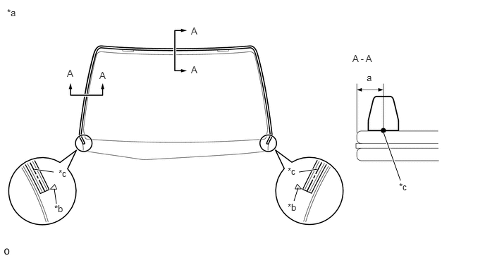
| *a | Back of Windshield Glass | *b | Ceramic Notch |
| *c | Window Glass Adhesive Dam Center Line | - | - |
- Standard:
Area Measurement a 4.6 mm (0.181 in.)
- NOTICE:
-
Install the upper windshield outside moulding after Primer G has been allowed to dry (approximately 3 min).
56118A
5.INSTALL NO. 2 WINDOW GLASS ADHESIVE DAM
Apply Primer G to the No. 2 window glass adhesive dam installation area on the windshield glass.
- NOTICE:
-
Do not apply too much Primer G.
When removing the peeling paper of a new No. 2 window glass adhesive dam, make sure that it does not contact the adhesive surface.
- NOTICE:
-
Install the No. 2 window glass adhesive dam after Primer G has been allowed to dry (approximately 3 min).
Install the No. 2 window glass adhesive dam to the windshield glass in the location shown in the illustration.
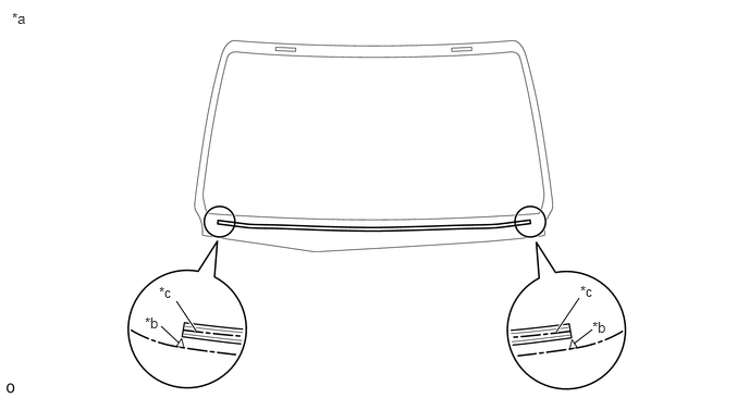
| *a | Back of Windshield Glass | *b | Ceramic Notch |
| *c | Window Glass Adhesive Dam Center Line | - | - |
56111
6.INSTALL WINDSHIELD GLASS
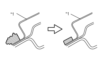
| *1 | Vehicle Body |

|
Adhesive |
Clean and shape the contact surface of the vehicle body.
On the contact surface of the vehicle body, use a knife to cut away excess adhesive as shown in the illustration.
- HINT:
-
Leave as much adhesive on the vehicle body as possible.
- NOTICE:
-
Be careful not to damage the vehicle body.
Clean the contact surface of the vehicle body with cleaner.
- HINT:
-
Even if all the adhesive has been removed, clean the vehicle body.
Windshield glass preliminary installation procedures.
Install the suction cups to the windshield glass.
Temporarily place the windshield glass onto the vehicle body and set it so that the gap between the body and the upper portion and sides of the windshield glass is even.
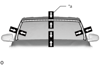
| *a | Matchmarks |
When using a new windshield glass:
Place adhesive tape on the windshield glass and body panel and use a pen to place matchmarks for installation.
- NOTICE:
-
From the interior, check that the No. 2 windshield glass stopper and vehicle body are attached.
- HINT:
-
When reusing a windshield glass, check the position of the matchmarks and make adjustments.
Remove the windshield glass.
Apply Primer M to the exposed part of the vehicle body.
- NOTICE:
- ·
Do not apply too much Primer M.
·Do not apply Primer M to the adhesive.
·Be careful when applying primer to the panel joints and spot welds.
Apply primer G to the windshield glass in the locations shown in the illustration.
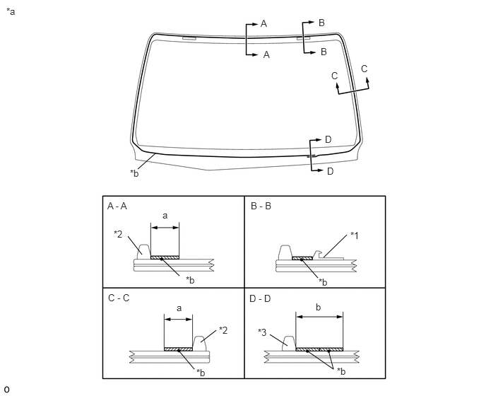
| *1 | No. 2 Windshield Glass Stopper | *2 | Window Glass Adhesive Dam |
| *3 | No. 2 Window Glass Adhesive Dam | - | - |
| *a | Back of Windshield Glass | *b | Adhesive Application Center Line |
|
|
Primer G Application Area | - | - |
- Standard:
Area Measurement a 11.0 mm (0.433 in.) or more b 19.0 mm (0.748 in.) or more
- NOTICE:
-
Do not apply too much Primer G.
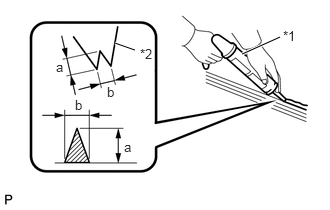
| *1 | Sealer Gun |
| *2 | Nozzle |
Cut off the tip of a cartridge nozzle as shown in the illustration.
- Standard:
Area Measurement a 12.0 mm (0.472 in.) b 8.0 mm (0.315 in.)
Load a sealer gun with the cartridge.
Apply a bead of adhesive to the location shown in the illustration.
- NOTICE:
-
Apply the adhesive after Primer G has been allowed to dry (approximately 3 min).
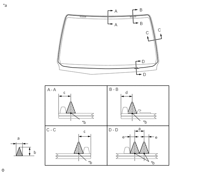
| *a | Back of Windshield Glass | *b | Adhesive Application Center Line |
|
|
Adhesive | - | - |
- Standard:
Area Measurement a 8.0 mm (0.315 in.) b 12.0 mm (0.472 in.) c 11.1 mm (0.437 in.) d 10.0 mm (0.394 in.) e 4.0 mm (0.157 in.)
Install windshield glass.
Using suction cups, position the windshield glass so that the matchmarks are aligned and install the windshield glass.
- NOTICE:
-
Install the windshield glass after Primer M on the vehicle body has been allowed to dry (approximately 3 min).
Lightly press the front surface of the windshield glass so that it is securely fit to the vehicle body.
- HINT:
-
Press the glass with a force of 98 N (10 kgf, 22 lbf) or more.
Using a scraper, remove any excess adhesive or apply as necessary.
- NOTICE:
-
Apply adhesive up to the edge of the windshield glass.
Remove any excess adhesive before it hardens.
Hold the windshield glass in place securely with protective tape or equivalent until the adhesive hardens.
- HINT:
-
Follow the instructions for each adhesive manufacturer or the corresponding owner's manual for the minimum amount of time necessary prior to driving the vehicle.
7.CHECK FOR LEAKS AND REPAIR
Conduct a leak test after the adhesive has completely hardened.
Seal any leaks with auto glass sealer.
Remove any protective or adhesive tape.
86101
8.CONNECT ANTENNA CORD SUB-ASSEMBLY (w/ Television Antenna)
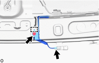
Attach the guide and install the bolt.
Connect the connector.
63310
9.INSTALL ROOF HEADLINING ASSEMBLY
for Double Cab:
Click hereVehicle Interior>INTERIOR PANELS / TRIM>ROOF HEADLINING(for Double Cab)>INSTALLATION
for Single Cab:
Click hereVehicle Interior>INTERIOR PANELS / TRIM>ROOF HEADLINING(for Single Cab)>INSTALLATION
for Smart Cab:
Click hereVehicle Interior>INTERIOR PANELS / TRIM>ROOF HEADLINING(for Smart Cab)>INSTALLATION
74610A
10.INSTALL ASSIST GRIP SUB-ASSEMBLY
74320
11.INSTALL VISOR ASSEMBLY LH
74310
12.INSTALL VISOR ASSEMBLY RH
74325
13.INSTALL VISOR BRACKET COVER LH
74325
14.INSTALL VISOR BRACKET COVER RH
81240
15.INSTALL NO. 1 ROOM LIGHT ASSEMBLY
81260A
16.INSTALL MAP LIGHT ASSEMBLY
87810
17.INSTALL INNER REAR VIEW MIRROR ASSEMBLY
62212
18.INSTALL FRONT PILLAR GARNISH LH
62211
19.INSTALL FRONT PILLAR GARNISH RH
74610A
20.INSTALL ASSIST GRIP SUB-ASSEMBLY (w/ Assist Grip)
55781E
21.INSTALL COWL TOP VENTILATOR LOUVER SUB-ASSEMBLY
53866J
22.INSTALL FRONT FENDER TO COWL SIDE SEAL RH
53867H
23.INSTALL FRONT FENDER TO COWL SIDE SEAL LH
- HINT:
-
Use the same procedure described for the RH side.
53885G
24.INSTALL FENDER APRON MUDGUARD SEAL SUB-ASSEMBLY RH
53886G
25.INSTALL FENDER APRON MUDGUARD SEAL SUB-ASSEMBLY LH
- HINT:
-
Use the same procedure described for the RH side.
26.INSTALL FRONT WIPER ARM AND BLADE ASSEMBLY LH
27.INSTALL FRONT WIPER ARM AND BLADE ASSEMBLY RH
85292B
28.INSTALL FRONT WIPER ARM HEAD CAP
29.CONNECT CABLE TO NEGATIVE BATTERY TERMINAL
- NOTICE:
-
When disconnecting the cable, some systems need to be initialized after the cable is reconnected.
-
Click hereGeneral>INTRODUCTION>REPAIR INSTRUCTION>INITIALIZATION