2TR-FBE FUEL FUEL INJECTOR INSTALLATION
PROCEDURE

 23250
1.INSTALL FUEL INJECTOR ASSEMBLY
- HINT:
-
Perform "Inspection After Repair" after replacing the fuel injector assembly.
-
Click hereEngine / Hybrid System>2TR-FBE ENGINE CONTROL>SFI SYSTEM>INITIALIZATION
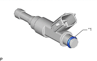
| *1 | O-Ring |
Apply a light coat of gasoline or spindle oil to new O-rings, and then install one to each fuel injector.
Apply a light coat of gasoline or spindle oil to the contact surfaces of the fuel delivery pipe and the O-ring of the fuel injector.
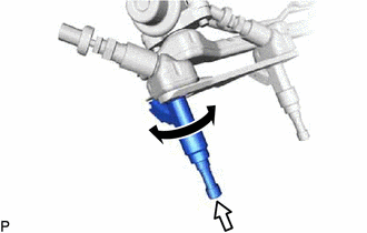

|
Turn |

|
Push |
Apply a light coat of gasoline or spindle oil to the O-ring again, and then install the fuel injector to the fuel delivery pipe by turning it right and left.
- NOTICE:
-
Make sure that the O-ring is not cracked or jammed when installing it.
Check that the fuel injector rotates smoothly.
If the fuel injector does not rotate, replace the O-ring.
23814B
2.INSTALL FUEL DELIVERY PIPE WITH FUEL INJECTOR ASSEMBLY
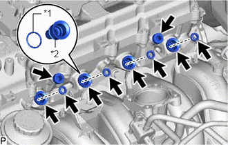
| *1 | O-Ring |
| *2 | Spacer |
Apply a light coat of gasoline or spindle oil to new O-rings, and then install one to each spacer.
Install the 4 spacers to the cylinder head.
Install 4 new injector vibration insulators to the cylinder head.
Install the 2 No. 1 delivery pipe spacers to the cylinder head.
Install the fuel delivery pipe together with the 4 fuel injectors, and then temporarily install the fuel delivery pipe with the 2 bolts.
- NOTICE:
-
Do not drop the fuel injectors when installing the fuel delivery pipe.
Check that the fuel injectors rotate smoothly.
If any fuel injector does not rotate, replace its O-ring.
Tighten the 2 bolts.
- Torque:
- 12 N*m (122 kgf*cm, 9 ft.*lbf)
Install the vacuum hose.
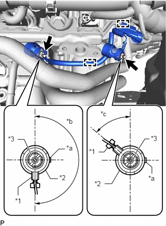
| *a | Rib |
| *b | 170 to 190° |
| *c | 40 to 60° |
| *1 | Wire Harness |
| *2 | Fuel Pipe Support |
| *3 | Glow Plug Assembly |
Install the 2 fuel pipe supports to each glow plug assembly as shown in the illustration.
Connect the No. 2 glow plug connector to each glow plug assembly and install with the 2 nuts as shown in the illustration.
- Torque:
- 2.2 N*m (22 kgf*cm, 19 in.*lbf)
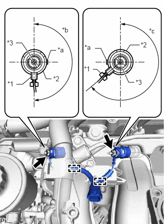
| *a | Rib |
| *b | 170 to 190° |
| *c | 220 to 240° |
| *1 | Wire Harness |
| *2 | Fuel Pipe Support |
| *3 | Glow Plug Assembly |
Install the 2 fuel pipe supports to each glow plug assembly as shown in the illustration.
Connect the No. 1 glow plug connector to each glow plug assembly and install with the 2 nuts as shown in the illustration.
- Torque:
- 2.2 N*m (22 kgf*cm, 19 in.*lbf)
Install the 4 glow plug screw grommets.
Connect the wire harness connector of the No. 2 glow plug connector.
Connect the wire harness connector of the No. 1 glow plug connector.
Connect the purge VSV connector.
Connect the 4 fuel injector connectors.
Connect the 4 wire harness clamps.
23270
3.INSTALL FUEL PRESSURE PULSATION DAMPER ASSEMBLY
23273H
4.CONNECT NO. 2 FUEL HOSE
Connect the No. 2 fuel hose.
23271H
5.CONNECT NO. 1 FUEL HOSE
Connect the No. 1 fuel hose.
Click hereEngine / Hybrid System>2TR-FBE FUEL>FUEL SYSTEM>PRECAUTION
22030
6.INSTALL THROTTLE BODY WITH MOTOR ASSEMBLY
7.CONNECT CABLE TO NEGATIVE BATTERY TERMINAL
- NOTICE:
-
When disconnecting the cable, some systems need to be initialized after the cable is reconnected.
-
Click hereGeneral>INTRODUCTION>REPAIR INSTRUCTION>INITIALIZATION
8.INSPECT FOR FUEL LEAK
Make sure that there are no fuel leaks after performing maintenance on the fuel system.
Connect the GTS to the DLC3.
Turn the ignition switch to ON and turn the GTS on.
- NOTICE:
-
Do not start the engine.
Enter the following menus: Powertrain / Engine and ECT / Active Test / Control the Fuel Pump / Speed.
- Powertrain > Engine and ECT > Active Test
-
Tester Display Control the Fuel Pump / Speed - 50004 234 5
Check that there are no leaks from the fuel system.
If there are fuel leaks, repair or replace parts as necessary.
Turn the ignition switch off.
Disconnect the GTS from the DLC3.