2TR-FBE FUEL FUEL INJECTOR REMOVAL
CAUTION / NOTICE / HINT
The necessary procedures (adjustment, calibration, initialization, or registration) that must be performed after parts are removed, installed, or replaced during the fuel injector assembly removal/installation are shown below.
| Replacement Part or Procedure | Necessary Procedures | Effects/Inoperative when not Performed | Link |
|---|---|---|---|
·
Replacement of throttle with motor body assembly ·
Cleaning the deposits from the throttle with motor body assembly ·
Replacement of fuel injector assembly |
Inspection after repair | Poor idle, engine start, etc. | ( ) |
PROCEDURE

 1.DISCHARGE FUEL SYSTEM PRESSURE
2. PRECAUTION
- NOTICE:
-
After turning the ignition switch off, waiting time may be required before disconnecting the cable from the battery terminal. Therefore, make sure to read the disconnecting the cable from the battery terminal notice before proceeding with work.
-
Click hereGeneral>INTRODUCTION>REPAIR INSTRUCTION>PRECAUTION
3.DISCONNECT CABLE FROM NEGATIVE BATTERY TERMINAL
- NOTICE:
-
When disconnecting the cable, some systems need to be initialized after the cable is reconnected.
-
Click hereGeneral>INTRODUCTION>REPAIR INSTRUCTION>INITIALIZATION
22030
4.REMOVE THROTTLE BODY WITH MOTOR ASSEMBLY
23271H
5.DISCONNECT NO. 1 FUEL HOSE
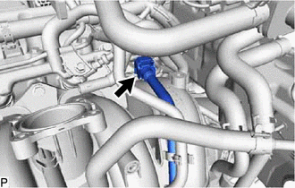
Disconnect the No. 1 fuel hose.
Click hereEngine / Hybrid System>2TR-FBE FUEL>FUEL SYSTEM>PRECAUTION
23273H
6.DISCONNECT NO. 2 FUEL HOSE
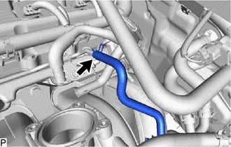
Disconnect the No. 2 fuel hose.
23270
7.REMOVE FUEL PRESSURE PULSATION DAMPER ASSEMBLY
23814B
8.REMOVE FUEL DELIVERY PIPE WITH FUEL INJECTOR ASSEMBLY
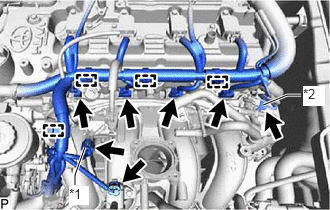
| *1 | No. 1 Glow Plug Connector |
| *2 | No. 2 Glow Plug Connector |
Disconnect the 4 wire harness clamps.
Disconnect the 4 fuel injector connectors.
Disconnect the purge VSV connector.
Disconnect the wire harness connector of the No. 1 glow plug connector.
Disconnect the wire harness connector of the No. 2 glow plug connector.
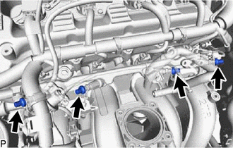
Remove the 4 glow plug screw grommets.
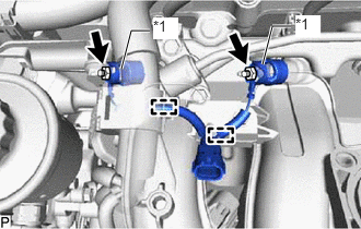
| *1 | Fuel Pipe Support |
Remove the 2 nuts.
Detach the 2 wire harness clamps and remove the No. 1 glow plug connector.
Remove the 2 fuel pipe supports.
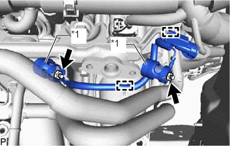
| *1 | Fuel Pipe Support |
Remove the 2 nuts.
Detach the 2 wire harness clamps and remove the No. 2 glow plug connector.
Remove the 2 fuel pipe supports.
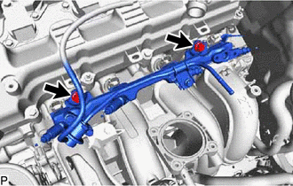
Remove the vacuum hose.
Remove the 2 bolts and fuel delivery pipe together with the 4 fuel injector assemblies.
- NOTICE:
-
Be careful not to drop the fuel injectors when removing the fuel delivery pipe.
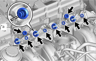
| *a | Protective Tape |
Remove the 2 No. 1 delivery pipe spacers.
Remove the 4 injector vibration insulators.
Using a screwdriver, remove the 4 spacers.
- HINT:
-
Tape the screwdriver tip before use.
Remove the O-ring from the spacer.
23250
9.REMOVE FUEL INJECTOR ASSEMBLY
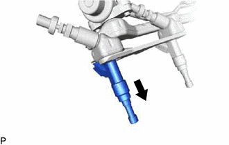

|
Pull Out |
Remove the 4 fuel injectors from the fuel delivery pipe.