Home › Drivetrain › VF2CM TRANSFER / 4WD / AWD › TOUCH SELECT 2-4 AND HIGH-LOW SYSTEM › from 2016.07
RM33J0E _52 Drivetrain _038470 VF2CM TRANSFER / 4WD / AWD _0197772 TOUCH SELECT 2-4 AND HIGH-LOW SYSTEM C

VF2CM TRANSFER / 4WD / AWD  TOUCH SELECT 2-4 AND HIGH-LOW SYSTEM  P2772  Four Wheel Drive (4WD) Low Switch Circuit Range / Performance  


DESCRIPTION

This DTC is output when a malfunction in the L4 detection switch is detected.

DTC No. Detection Item DTC Detection Condition Trouble Area
P2772 Four Wheel Drive (4WD) Low Switch Circuit Range / Performance
·

Diagnosis Condition: Ignition switch turned to ON (3 seconds elapse after ignition switch is turned to ON)

·

Malfunction Status: L4 detection switch is stuck OFF when the vehicle is in L4

·

Malfunction Time: 10 seconds or more

·

Other: 1 trip detection logic


·

Wire harness and connector

·

4 wheel drive control ECU

·

Transfer shift actuator assembly


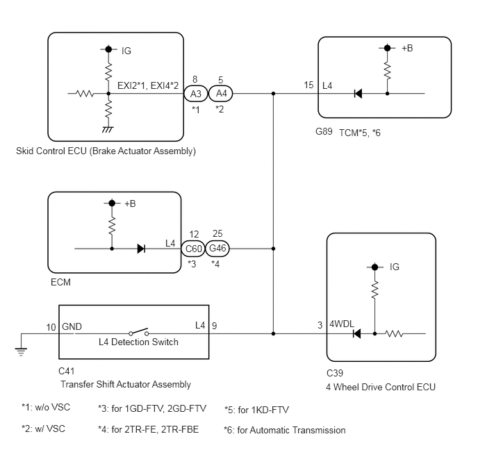
WIRING DIAGRAM

C337497E04
1.823,0.677 2.135,0.875 0.313,0.198 10 false IG 1.76,1.198 2.688,1.396 0.927,0.198 10 false EXI2*1, EXI4*2 2.854,1.323 3.167,1.521 0.313,0.198 10 false A3 3.24,1.313 3.552,1.51 0.313,0.198 10 false A4 2.885,1.104 3.042,1.302 0.156,0.198 10 false 8 3.271,1.115 3.427,1.313 0.156,0.198 10 false 5 2.875,1.563 3.188,1.76 0.313,0.198 10 false *1 3.229,1.552 3.542,1.75 0.313,0.198 10 false *2 0.24,2.177 3.063,2.417 2.823,0.24 10 false Skid Control ECU (Brake Actuator Assembly) 4.729,1.885 5.188,2.083 0.458,0.198 10 false G89 5.083,1.906 5.854,2.104 0.771,0.198 10 false TCM*5, *6 4.552,1.188 4.865,1.385 0.313,0.198 10 false 15 4.833,1.198 5.146,1.396 0.313,0.198 10 false L4 6.021,0.635 6.333,0.833 0.313,0.198 10 false +B 0.76,4.146 1.219,4.344 0.458,0.198 10 false ECM 1.865,2.969 2.177,3.167 0.313,0.198 10 false +B 2.479,3.563 2.792,3.76 0.313,0.198 10 false L4 2.781,3.646 3.24,3.844 0.458,0.198 10 false C60 2.833,3.427 3.146,3.625 0.313,0.198 10 false 12 2.813,3.875 3.125,4.073 0.313,0.198 10 false *3 3.167,3.875 3.479,4.073 0.313,0.198 10 false *4 3.135,3.635 3.594,3.833 0.458,0.198 10 false G46 3.188,3.417 3.5,3.615 0.313,0.198 10 false 25 0.688,4.823 1,5.021 0.313,0.198 10 false 10 0.927,4.813 1.385,5.01 0.458,0.198 10 false GND 1.479,5.042 2.781,5.219 1.302,0.177 10 false L4 Detection Switch 2.927,4.792 3.24,4.99 0.313,0.198 10 false L4 3.177,4.802 3.333,5 0.156,0.198 10 false 9 0.875,5.479 1.333,5.677 0.458,0.198 10 false C41 0.906,5.677 2.979,5.865 2.073,0.188 10 false Transfer Shift Actuator Assembly 4.76,4.792 4.917,4.99 0.156,0.198 10 false 3 4.938,4.771 5.552,4.969 0.615,0.198 10 false 4WDL 5.844,3.917 6.156,4.115 0.313,0.198 10 false IG 4.896,5.51 5.354,5.708 0.458,0.198 10 false C39 4.885,5.719 6.594,5.896 1.708,0.177 10 false 4 Wheel Drive Control ECU 0.323,6.021 1.188,6.198 0.865,0.177 10 false *1: w/o VSC 0.323,6.344 1.854,6.542 1.531,0.198 10 false *2: w/ VSC 1.469,6.042 3.188,6.219 1.719,0.177 10 false *3: for 1GD-FTV, 2GD-FTV 1.469,6.354 3.615,6.552 2.146,0.198 10 false *4: for 2TR-FE, 2TR-FBE 3.365,6.063 4.469,6.25 1.104,0.188 10 false *5: for 1KD-FTV 3.354,6.365 5.281,6.531 1.927,0.167 10 false *6: for Automatic Transmission

PROCEDURE

1.CHECK HARNESS AND CONNECTOR (4 WHEEL DRIVE CONTROL ECU - TRANSFER SHIFT ACTUATOR ASSEMBLY)
a.

Disconnect the C39 4 wheel drive control ECU connector.


b.

Disconnect the C41 transfer shift actuator assembly connector.

c.

w/o VSC:

Disconnect the A3 skid control ECU (brake actuator assembly) connector.

w/ VSC:

Disconnect the A4 skid control ECU (brake actuator assembly) connector.


d.

for 1GD-FTV, 2GD-FTV:

Disconnect the C60 ECM connector.

for 2TR-FE, 2TR-FBE:

Disconnect the G46 ECM connector.

for 1KD-FTV (Automatic Transmission):

Disconnect the G89 TCM connector.


e.

Measure the resistance according to the value(s) in the table below.

Standard Resistance:
Tester Connection Condition Specified Condition
C39-3 (4WDL) - C41-9 (L4) Always Below 1 Ω
C41-10 (GND) - Body ground Always Below 1 Ω
C39-3 (4WDL) or C41-9 (L4) - Body ground Always 10 kΩ or higher


Result:
Proceed to
OK
NG


OK

2.CHECK TRANSFER SHIFT ACTUATOR ASSEMBLY

NG

REPAIR OR REPLACE HARNESS OR CONNECTOR

2.CHECK TRANSFER SHIFT ACTUATOR ASSEMBLY
a.

Turn the ignition switch to ON.


b.

Turn the transfer position switch to L4.


c.

Turn the ignition switch off.


d.

Disconnect the C41 transfer shift actuator assembly connector.


e.
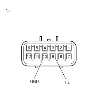
C325774C06
1.865,1.958 2.24,2.688 false 1.479,1.958 1.167,2.667 false 0.198,0.271 0.51,0.469 0.313,0.198 10 false *a 1.021,2.688 1.479,2.885 0.458,0.198 10 false GND 2.219,2.729 2.531,2.927 0.313,0.198 10 false L4
*a Component without harness connected
(Transfer Shift Actuator Assembly)


Measure the resistance according to the value(s) in the table below.

Standard Resistance:
Tester Connection Condition Specified Condition
9 (L4) - 10 (GND) Transfer L4 Below 1 Ω


Result:
Proceed to
OK
NG


OK

REPLACE 4 WHEEL DRIVE CONTROL ECU

NG

REPLACE TRANSFER SHIFT ACTUATOR ASSEMBLY