SEAT REAR NO. 2 SEAT ASSEMBLY REASSEMBLY
CAUTION / NOTICE / HINT
- CAUTION:
- ·
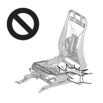
Wear protective gloves. Sharp areas on the parts may injure your hands.
·There is risk of injury.
·Replace any other damaged parts as necessary.
- HINT:
- ·
Use the same procedure for the RH and LH sides.
·The procedure listed below is for the RH side.
PROCEDURE

 79203A
1.INSTALL NO. 2 SEATBACK FRAME SUB-ASSEMBLY RH
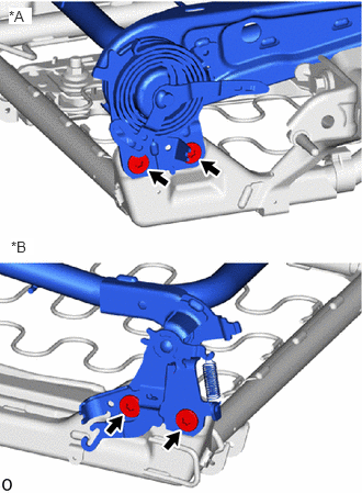
| *A | for RH side |
| *B | for LH side |
Using a T55 "TORX" socket wrench, install the 4 "TORX" bolts and rear No. 2 seat hinge sub-assembly RH.
- Torque:
- 42 N*m (428 kgf*cm, 31 ft.*lbf)
71303B
2.INSTALL REAR NO. 2 SEAT HINGE SUB-ASSEMBLY RH
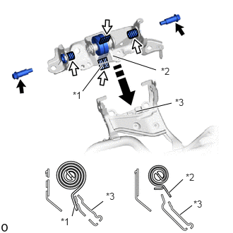
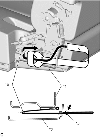
| *1 | Spring A |
| *2 | Spring B |
| *3 | Bracket |

|
Apply Grease |

|
Install in this Direction |
Apply grease to the position shown in the illustration.
Set spring A to the lower part of the bracket.
Set spring B to the upper part of the bracket.
While pushing in the installation direction shown in the illustration, align the position of the bolt installation holes.
- NOTICE:
-
Install the spring carefully, as it is under tension.
Install the rear No. 2 seat hinge sub-assembly RH with the 2 bolts.
- Torque:
- 21 N*m (214 kgf*cm, 15 ft.*lbf)
71691B
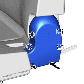
3.INSTALL REAR OUTER SEAT LOCK COVER RH
|
|
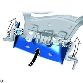
Install in this Direction (1) |

|
Install in this Direction (2) |
Push in the installation direction (1) shown in the illustration to temporarily install the rear outer seat lock cover RH.
Push the rear outer seat lock cover RH in the installation direction (2) shown in the illustration to attach the guide and install the rear outer seat lock cover RH.
72695B
4.INSTALL REAR SEAT LOCK CONTROL CABLE RH
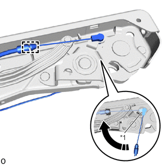
| *1 | Cable End |
|
|
Install in this Direction |
Turn the cable end in the install direction shown in the illustration and connect the cable end to install the rear seat lock control cable RH.
- HINT:
-
Pass the rear seat lock control cable RH through the hole in the leg frame.
Attach the casing cap.
- HINT:
-
Install at the yellow casing cap side.
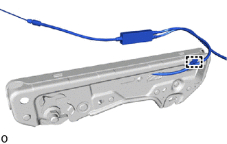
Attach the clamp.
79236A
5.INSTALL NO. 2 SEAT LEG COVER
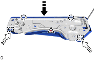
|
|
Install in this Direction (1) |
|
|
Install in this Direction (2) |
Push in the installation direction (1) shown in the illustration to attach the claw.
While pushing the plate in the installation direction (2), attach the guide.
Attach the clip to install the No. 2 seat leg cover.
79030B
6.INSTALL REAR NO. 2 SEAT LEG ASSEMBLY RH
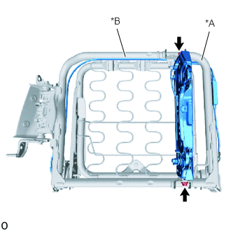
| *A | Installation Position A |
| *B | Installation Position B |
Install the 2 bolts and rear No. 2 seat leg assembly RH.
Move a screwdriver with its tip wrapped with protective tape in the direction indicated by the arrow to widen the spring and install the hook part.
Temporarily install the rear seat lock control cable RH along the No. 2 seat cushion frame sub-assembly RH.
- HINT:
- ·
At installation position A, pass the cable below the pipe.
- ·
At installation position B, pass the cable above the pipe.
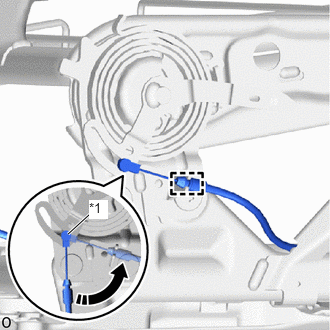
| *1 | Cable End |
|
|
Install in this Direction |
for RH side:
Turn the cable end in the install direction shown in the illustration and connect the cable end.
Attach the casing cap.
- HINT:
-
Install at the purple casing cap side.
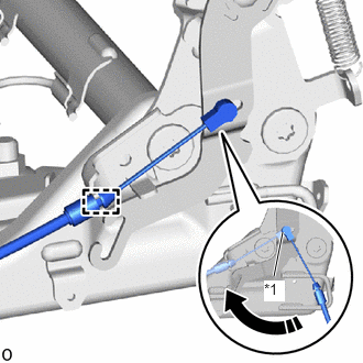
| *1 | Cable End |
|
|
Install in this Direction |
for LH side:
Turn the cable end in the install direction shown in the illustration and connect the cable end.
Attach the casing cap.
- HINT:
-
Install at the natural casing cap side.
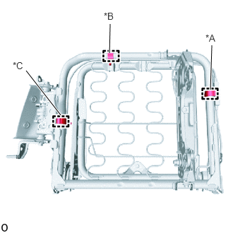
| *A | Installation Position A |
| *B | Installation Position B |
| *C | Installation Position C |
Attach the 3 wiring harness clamps.
- HINT:
- ·
At installation position A, align the marking of the cable joint.
- ·
At installation position B, secure at the white positioning tape of the cable.
- ·
At installation position C, align and secure at the curved end of the pipe.
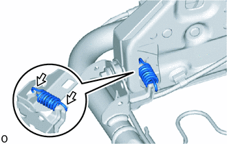

|
MP Grease |
Apply grease to both ends of the spring.
Install the spring to the No. 2 seat leg assembly RH.
- HINT:
-
Install the spring facing the same direction shown in the illustration.
73580A
7.INSTALL REAR NO. 2 SEAT INNER BELT SUB-ASSEMBLY
79117A
8.INSTALL REAR NO. 2 SEAT CUSHION CARPET RH
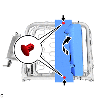
|
|
Install in this Direction |
Move the rear No. 2 seat leg assembly RH as shown in the illustration.
Attach the clip and install the rear No. 2 seat cushion carpet RH.
71693
9.INSTALL REAR SEAT LOWER CUSHION HINGE COVER RH
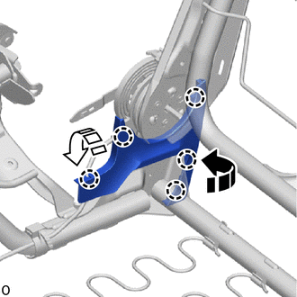
|
|
Install in this Direction (1) |
|
|
Install in this Direction (2) |
While rotating the part in install direction (1) shown in the illustration attach the claw.
While rotating the part in install direction (2) shown in the illustration, attach the claw to rear seat lower cushion hinge cover RH.
10.INSTALL SEAT COVER WIRE
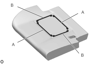
Install the seat cover wire.
- HINT:
- ·
There are service parts available for wires of 1000 mm or longer and formed wires.
- ·
When a wire that is less than 1000 mm (3.28 ft.) in length is needed, cut and shape a 1000 mm supplied wire into the dimensions shown in the illustration.
- ·
Refer to the precautions when creating a wire.
Click hereVehicle Interior>SEAT>FRONT SEAT ASSEMBLY(for Manual Seat)>PRECAUTION
- Length:
A 270 mm (10.63 in.) B 200 mm (7.88 in.)
- HINT:
-
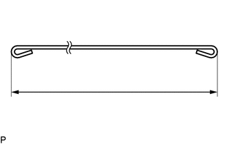
-
The dimensions shown in the illustration are the length.
79021
11.INSTALL NO. 2 CUSHION COVER SUB-ASSEMBLY RH
- HINT:
- ·
Refer to the precautions on wrinkles to avoid creating any on the No. 2 cushion cover sub-assembly RH when installing the seat cover.
Click hereVehicle Interior>SEAT>FRONT SEAT ASSEMBLY(for Manual Seat)>PRECAUTION
- ·
As shown in the illustration, fix all of the cover seam allowances in the same direction.
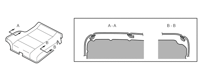 0.594,0.823 0.75,1.021 0.156,0.198 10 false A 1.625,1.427 1.781,1.625 0.156,0.198 10 true B 1.896,1.583 2.052,1.781 0.156,0.198 10 true B 3.833,0.823 4.604,1.021 0.771,0.198 10 false A - A 5.927,0.823 6.698,1.021 0.771,0.198 10 false B - B
Temporarily install the No. 2 cushion cover sub-assembly RH to the No. 2 seat cushion pad RH.
Using hog ring pliers, install the No. 2 cushion cover sub-assembly RH to the No. 2 seat cushion pad RH with 8 new hog rings in the order shown in the illustration.
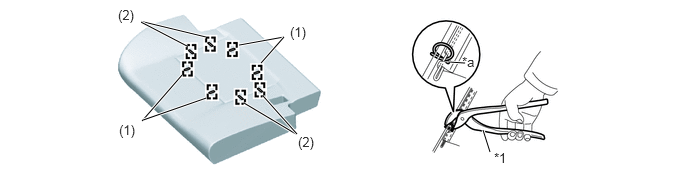
| *1 | Hog Ring Pliers | - | - |
| *a | Cutout | - | - |
Using hog ring pliers, connect the 2 straps of the No. 2 cushion cover sub-assembly RH to the No. 2 seat cushion pad RH with 6 new hog rings.
- HINT:
- ·
Do not dirty or damage the No. 2 cushion cover sub-assembly RH.
- ·
Securely tighten the hog rings as shown in the illustration while making sure wrinkles do not form in the center of the fabric and No. 2 seat cushion pad RH.
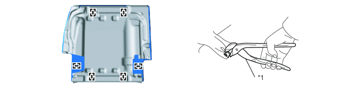
| *1 | Hog Ring Pliers | - | - |
12.INSTALL SEAT CUSHION COVER WITH PAD
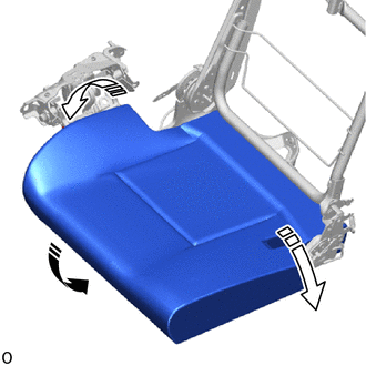
|
|
Install in this Direction (1) |
|
|
Install in this Direction (2) |
Push in the front of the seat cushion cover with pad in the installation direction (1).
While slightly pulling up both sides of the seat cushion cover with pad, push them in the installation direction (2) shown in the illustration.
79378A
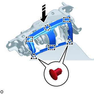
13.INSTALL NO. 3 SEAT CUSHION HINGE COVER RH
|
|
Install in this Direction |
While aligning the guide and claw, push them in as shown in the illustration.
Attach the clip to install the No. 3 seat cushion hinge cover RH.
72065A
14.INSTALL REAR SEAT CUSHION LOCK HOOK SUB-ASSEMBLY RH
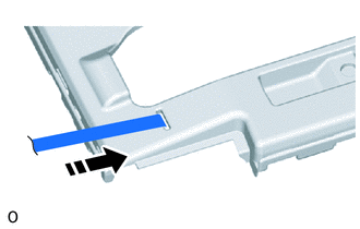
|
|
Install in this Direction |
Pass the rear seat cushion lock hook subassembly RH through the hole of the No. 2 seat cushion cover as shown in the illustration.
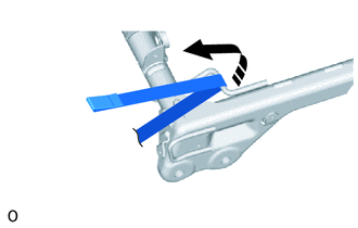
|
|
Install in this Direction |
Pass the rear seat cushion lock hook sub-assembly RH between the wire of the No. 2 seat cushion frame sub-assembly RH as shown in the illustration.
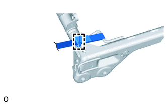
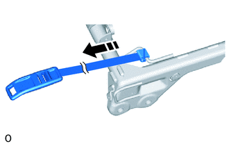
Pass a cable tie through the loop at the end of the rear seat cushion lock hook sub-assembly RH and bind the top and bottom of the rear seat cushion lock hook sub-assembly.
|
|
Install in this Direction |
Pull to install the rear seat cushion lock hook sub-assembly RH as shown in the illustration.
Cut the cable tie at the cross-hatched part.
79952
15.INSTALL NO. 2 SEAT CUSHION COVER
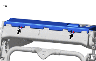
| *A | for Rear Side |
Set the No. 2 seat cushion cover to the No. 2 seat cushion frame sub-assembly RH.
Install the 2 screws.
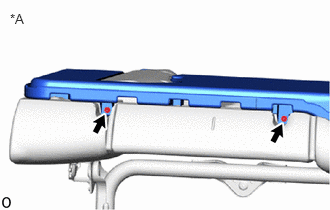
| *A | for Front Side |
Install the 2 screws.
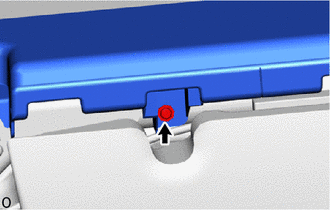
Install the screw.
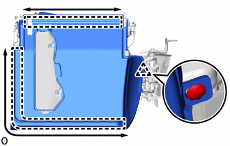
While sliding the part in the direction indicated by the arrow shown in the illustration to attach the J hook.
Install the clip to No. 2 seat cushion cover.
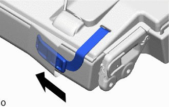
Push in the rear seat cushion lock hook sub-assembly RH the rear end of the seat cushion with pad.
16.INSTALL SEAT COVER WIRE
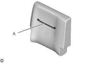
Install the seat cover wire.
- HINT:
- ·
There are service parts available for wires of 1000 mm or longer and formed wires.
- ·
When a wire that is less than 1000 mm (3.28 ft.) in length is needed, cut and shape a 1000 mm supplied wire into the dimensions shown in the illustration.
- ·
Refer to the precautions when creating a wire.
Click hereVehicle Interior>SEAT>FRONT SEAT ASSEMBLY(for Manual Seat)>PRECAUTION
- Length:
A 270 mm (10.63 in.)
- HINT:
-
-
The dimensions shown in the illustration are the length.
79023
17.INSTALL NO. 2 SEATBACK COVER SUB-ASSEMBLY RH
- HINT:
- ·
Refer to the precautions on wrinkles to avoid creating any on the No. 2 seatback cover sub-assembly RH when installing the seat cover.
Click hereVehicle Interior>SEAT>FRONT SEAT ASSEMBLY(for Manual Seat)>PRECAUTION
- ·
As shown in the illustration, fix all of the cover seam allowances in the same direction.
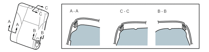 0.271,0.656 0.427,0.854 0.156,0.198 10 false A 0.552,0.76 0.708,0.958 0.156,0.198 10 false A 1.135,0.969 1.313,1.146 0.177,0.177 10 true B 1.406,1.042 1.583,1.219 0.177,0.177 10 true B 1.344,0.396 1.521,0.573 0.177,0.177 10 true C 1.542,0.188 1.719,0.365 0.177,0.177 10 true C 2.396,0.292 3.167,0.49 0.771,0.198 10 false A - A 4.115,0.302 4.885,0.5 0.771,0.198 10 false C - C 5.406,0.302 6.177,0.5 0.771,0.198 10 false B - B
Set the No. 2 seatback cover sub-assembly RH.
Using hog ring pliers, install the No. 2 seatback cover sub-assembly RH with 3 new hog rings.
- HINT:
- ·
Do not dirty or damage the No. 2 seatback cover sub-assembly RH.
- ·
Securely tighten the hog rings as shown in the illustration while making sure wrinkles do not form in the center of the fabric and No. 2 seatback pad RH.
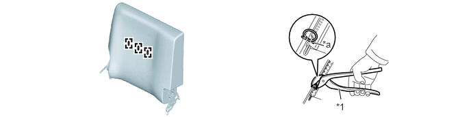 5.188,1.521 5.156,1.354 true 4.927,0.698 4.781,0.656 true 4.906,0.594 5.219,0.792 0.313,0.198 10 false *a 5.115,1.552 5.427,1.75 0.313,0.198 10 false *1
*1 Hog Ring Pliers - - *a Cutout - -
18.INSTALL SEATBACK COVER WITH PAD
|
|
Install in this Direction (1) |
|
|
Install in this Direction (2) |
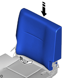
Push the seatback cover with pad in the installation direction (1) shown in the illustration.
Push the bottom part of the seatback cover with pad in the installation direction (2) to install the seatback cover with pad.
71931C
19.INSTALL REAR NO. 2 SEAT HEADREST SUPPORT ASSEMBLY
|
|
Install in this Direction |
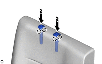
Attach the claw and push in the install direction shown in the illustration to install the 2 rear No. 2 seat headrest support assemblies.
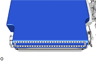
While sliding the part in the direction indicated by the arrow shown in the illustration to attach the J hook.
79393
20.INSTALL REAR NO. 2 SEATBACK CUSHION
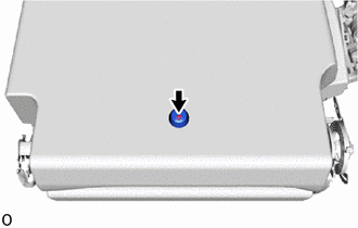
Install the screw and rear No. 2 seatback cushion.
71843A
21.INSTALL REAR NO. 2 SEAT RECLINING COVER RH
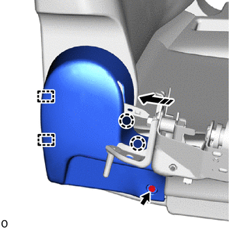
|
|
Install in this Direction |
Pass the rear No. 2 seat reclining cover RH through the installation part of the reclining adjuster release handle RH and push to attach the claw and guide as shown in the illustration.
Install the screw.
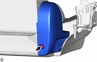
Install the screw to rear No. 2 seat reclining cover RH.
72525A
22.INSTALL RECLINING ADJUSTER RELEASE HANDLE RH
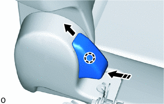
|
|
Install in this Direction |
While pulling up in the direction of the arrow, push as shown in the illustration to attach the claw and install the reclining adjuster release handle RH.
72525D
23.INSTALL NO. 2 RECLINING ADJUSTER RELEASE HANDLE RH
| *1 | No. 2 Seat Cushion Frame Sub-Assembly RH |
| *2 | Rear Seat Lower Cushion Hinge Cover RH |
| *3 | Rear Seatback Lock Release Button |
| *a | Resin portion of link |
|
|
Install in this Direction |
Pull the No. 2 reclining adjuster release handle RH in the direction of the cushion wire part of the No. 2 seat cushion frame sub-assembly RH as shown in the illustration to install the No. 2 reclining adjuster release handle RH.
Hook the No. 2 reclining adjuster release handle RH on the resin portion of the link.
Pass the No. 2 reclining adjuster release handle RH through the hole of the rear seat lower cushion hinge cover RH.
Install the new rear seatback lock release button.
71693
24.INSTALL REAR SEAT LOWER CUSHION HINGE COVER RH
|
|
Install in this Direction |
Push as shown in the illustration to attach the claw and guide.
Install the screw to rear seat lower cushion hinge cover RH.