5L-E ENGINE MECHANICAL TIMING BELT REMOVAL
CAUTION / NOTICE / HINT
The necessary procedures (adjustment, calibration, initialization or registration) that must be performed after parts are removed, installed or replaced during the timing belt removal/installation are shown below.
| Replacement Part or Procedure | Necessary Procedures | Effects/Inoperative when not Performed | Link |
|---|---|---|---|
| Replacement of timing belt | Mode reset operation | ·
Does not illuminate when replacement is necessary ·
Illuminates when replacement is not necessary |
( ) |
- CAUTION:
-
-
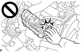
To prevent burns, do not touch the engine, exhaust manifold or other high temperature components while the engine is hot.
PROCEDURE

 51410
1.REMOVE NO. 1 ENGINE UNDER COVER ASSEMBLY
2.REMOVE COMPRESSOR ASSEMBLY WITH MAGNET CLUTCH
3.DRAIN ENGINE COOLANT
44310A
4.REMOVE VANE PUMP V BELT
88320
5.REMOVE COOLER COMPRESSOR V BELT
16361A
6.REMOVE FAN AND GENERATOR V BELT
16571C
7.REMOVE NO. 1 RADIATOR HOSE
44360
8.DISCONNECT VANE PUMP OIL RESERVOIR ASSEMBLY
44369A
9.REMOVE OIL RESERVOIR BRACKET
16470
10.REMOVE RADIATOR RESERVOIR
16711
11.REMOVE FAN SHROUD
44319
12.REMOVE VANE PUMP DRIVE PULLEY
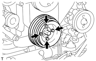
Remove the 4 bolts, vane pump drive pulley and cooler compressor drive pulley.
13471
13.REMOVE CRANKSHAFT PULLEY
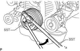
| *a | Hold |

|
Turn |
Using SST, hold the crankshaft pulley and loosen the crankshaft pulley bolt.
- SST
- 09213-54015 (91651-60855)
09330-00021
- HINT:
-
Make sure to leave the pulley bolt screwed into the crankshaft by 2 or 3 threads.
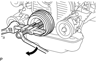
| *a | Hold |
|
|
Turn |
Using SST, remove the crankshaft pulley.
- SST
- 09950-50013 (09951-05010, 09952-05010, 09953-05020, 09954-05021)
88431
14.REMOVE NO. 1 COMPRESSOR MOUNTING BRACKET
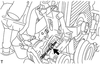
Remove the bolt and disconnect the generator with vacuum pump assembly.
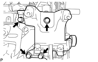
Remove the 4 bolts and No. 1 compressor mounting bracket.
11302
15.REMOVE TIMING BELT COVER
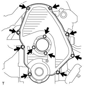
Remove the 11 bolts, washers, timing belt cover, and 2 timing belt cover gaskets.
13566A
16.REMOVE TIMING BELT GUIDE
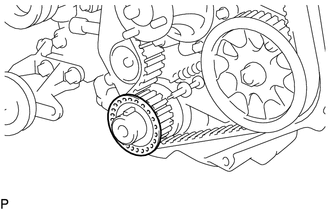
Remove the timing belt guide.
17.SET NO. 1 CYLINDER TO TDC/COMPRESSION
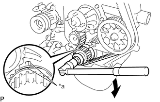
| *a | Timing Mark |
|
|
Turn |
Using the crankshaft pulley bolt, align the groove of the crankshaft pulley with the timing pointer by turning the crankshaft clockwise.
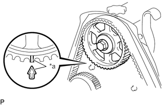
| *a | Timing Mark |
Check that the timing marks of the camshaft timing pulley and No. 2 timing belt cover are aligned.
If not, turn the crankshaft 1 revolution (360°).
13568
18.REMOVE TIMING BELT
- HINT:
-
If reusing the timing belt, draw a direction arrow on the timing belt (in the direction the belt moves when the engine is running), and place matchmarks on the pulleys and timing belt.
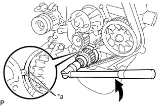
| *a | Timing Mark |
|
|
Turn |
Turn the crankshaft 90° counterclockwise, and align the timing mark of the crankshaft timing pulley with the protrusion of the timing belt case sub-assembly.
- NOTICE:
-
If the timing belt is disengaged, having the crankshaft timing pulley at the wrong angle can cause the piston head and valve head to come into contact with each other when removing the camshaft timing pulley, causing damage. Therefore, always set the crankshaft pulley at the correct angle.
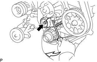

|
Pry |
Loosen the bolt, and shift the No. 1 timing belt idler sub-assembly to the left as far as possible.
Tighten the bolt, and then relieve the timing belt tension.
Remove the timing belt.
13505
19.REMOVE NO. 1 TIMING BELT IDLER SUB-ASSEMBLY
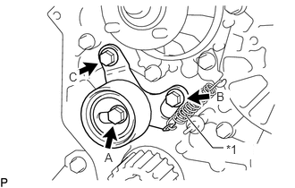
| *1 | Idler Tension Spring |
Remove the 2 bolts A and B.
Loosen bolt C, and remove the No. 1 timing belt idler sub-assembly and idler tension spring.
- HINT:
-
Bolt C is combined with the No. 1 timing belt idler sub-assembly.