5L-E FUEL FUEL INJECTION PUMP INSTALLATION
PROCEDURE

 22100
1.INSTALL INJECTION PUMP ASSEMBLY
Temporarily install the injection pump assembly to the timing gear case sub-assembly with the 2 nuts.
Temporarily install the No. 1 injection pump stay to the cylinder block sub-assembly and injection pump assembly with the 3 bolts.
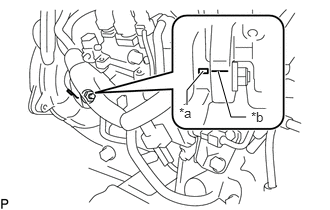
| *a | Mark (Timing Gear Case Sub-assembly Side) |
| *b | Mark (Injection Pump Assembly Side) |
Rotate the injection pump assembly body to align the marks on the injection pump assembly flange and timing gear case sub-assembly.
Tighten the 2 nuts.
- Torque:
- 20.5 N*m (209 kgf*cm, 15 ft.*lbf)
Tighten the 3 bolts.
- Torque:
- 26 N*m (265 kgf*cm, 19 ft.*lbf)
Connect the 7 connectors and attach the wire harness clamp.
Connect the 3 fuel hoses to the injection pump assembly, and slide the 3 clamps to secure the hoses.
13613P
2.INSTALL INJECTION PUMP DRIVE PULLEY
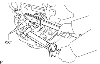
Using SST, install the injection pump drive pulley to the injection pump assembly with the nut.
- SST
- 09213-14010
09330-00021 (91651-60865)
- Torque:
- 63.7 N*m (650 kgf*cm, 47 ft.*lbf)
23701
3.INSTALL INJECTION PIPE SUB-ASSEMBLY
26100
4.INSTALL VENTURI ASSEMBLY
13568
5.INSTALL TIMING BELT
6.BLEED AIR FROM FUEL SYSTEM