2TR-FE ENGINE CONTROL CRANKSHAFT POSITION SENSOR INSTALLATION
PROCEDURE

 11301K
1.INSTALL CRANKSHAFT POSITION SENSOR
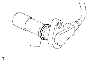
| *1 | O-Ring |
Apply a light coat of engine oil to the O-ring of the crankshaft position sensor.
Install the crankshaft position sensor with the bolt.
- Torque:
- 9.0 N*m (92 kgf*cm, 80 in.*lbf)
- NOTICE:
- ·
When reusing the crankshaft position sensor, inspect the O-ring.
·Make sure that the O-ring is not cracked or jammed when installing the crankshaft position sensor.
Connect the crankshaft position sensor connector to the connector bracket.
Attach the harness clamp.
Connect the crankshaft position sensor connector.
88431
2.INSTALL NO. 1 COMPRESSOR MOUNTING BRACKET
88320
3.CONNECT COOLER COMPRESSOR ASSEMBLY
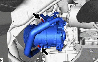
Using an E8 "TORX" socket wrench, temporarily connect the cooler compressor assembly with the 2 stud bolts.
Tighten the 2 stud bolts.
- Torque:
- 10 N*m (102 kgf*cm, 7 ft.*lbf)
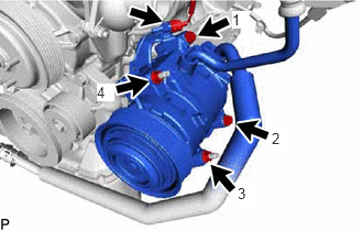
Tighten the 2 nuts and 2 bolts in the order shown in the illustration to connect the cooler compressor assembly.
- Torque:
- 24.5 N*m (250 kgf*cm, 18 ft.*lbf)
Connect the cooler compressor connector.
Connect the suction hose sub-assembly with the bolt.
- Torque:
- 5.4 N*m (55 kgf*cm, 48 in.*lbf)
53737B
4.INSTALL FRONT UPPER FENDER APRON SEAL LH
16361A
5.INSTALL FAN AND GENERATOR V BELT