1KD-FTV FUEL FUEL SUPPLY PUMP INSTALLATION
CAUTION / NOTICE / HINT
- NOTICE:
- ·
When replacing the parts in the following chart (A), replace the No. 1 injection pipe sub-assembly, No. 2 injection pipe sub-assembly, No. 3 injection pipe sub-assembly, No. 4 injection pipe sub-assembly and/or fuel inlet pipe sub-assembly with new ones.
Replaced Parts (A) Pipes Requiring New Replacement ·Injector assembly (including shuffling the injector assemblies between the cylinders)
·Common rail assembly
·Cylinder head sub-assembly
·No. 1 injection pipe sub-assembly
·No. 2 injection pipe sub-assembly
·No. 3 injection pipe sub-assembly
·No. 4 injection pipe sub-assembly
·Supply pump assembly
·Common rail assembly
·Cylinder block sub-assembly
·Cylinder head sub-assembly
·Cylinder head gasket
·Timing Gear Case Assembly
Fuel inlet pipe sub-assembly
·After removing the No. 1 injection pipe sub-assembly, No. 2 injection pipe sub-assembly, No. 3 injection pipe sub-assembly, No. 4 injection pipe sub-assembly and fuel inlet pipe sub-assembly, clean them with a brush and compressed air.
PROCEDURE

 22100
1.INSTALL FUEL SUPPLY PUMP ASSEMBLY
- NOTICE:
-
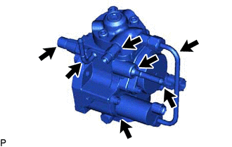
-
Do not hold the supply pump assembly by the parts indicated by the arrows in the illustration.
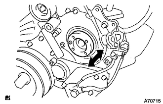
Check that the injection gear in the timing gear case assembly moves back and forth smoothly.
Install a new O-ring to the fuel supply pump assembly.
Apply a light coat of engine oil to the O-ring.
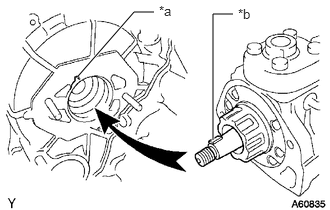
| *a | Groove |
| *b | Set Key |
Align the groove of the injection gear with the set key on the fuel supply pump drive shaft.
Install the fuel supply pump assembly with the 2 nuts.
- Torque:
- 21 N*m (214 kgf*cm, 15 ft.*lbf)
Set a new O-ring before tightening the set nut.
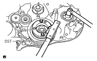
Using SST, hold the crankshaft pulley and install the set nut.
- SST
- 09213-58014 (91551-80840)
09330-00021
- Torque:
- 63.7 N*m (650 kgf*cm, 47 ft.*lbf)
Install the pump drive shaft pulley and No. 2 camshaft timing pulley flange with the 4 bolts.
- Torque:
- 31 N*m (316 kgf*cm, 23 ft.*lbf)
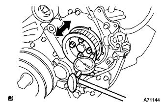
Move the pump drive shaft pulley back and forth to check the thrust clearance of the fuel supply pump drive shaft.
- Standard thrust clearance (reference):
0.15 to 0.55 mm (0.00590 to 0.0217 in.)
If there is no clearance, disassemble and reassemble the fuel supply pump assembly and pump drive shaft pulley. Then repeat the step above.
Connect the connector to the fuel temperature sensor.
Connect the connector to the suction control valve.
Connect the fuel hose and No. 1 fuel hose to the fuel supply pump assembly, and slide the 2 clamps to secure the hoses.
23804C
2.INSTALL FUEL INLET PIPE SUB-ASSEMBLY
Temporarily install the fuel inlet pipe sub-assembly with the union nuts.
- NOTICE:
- ·
When replacing the fuel supply pump assembly, it is necessary to replace the fuel inlet pipe sub-assembly with a new one.
·Keep the fuel inlet pipe sub-assembly free of foreign matter.
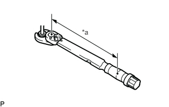
| *a | Torque Wrench Fulcrum Length |
Using a 17 mm union nut wrench, tighten the fuel inlet pipe sub-assembly union nut on the common rail assembly side.
- Torque:
- Specified tightening torque : 35 N*m (357 kgf*cm, 26 ft.*lbf)
- HINT:
- ·
Calculate the torque wrench reading when changing the fulcrum length of the torque wrench.
Click hereGeneral>INTRODUCTION>REPAIR INSTRUCTION>PRECAUTION
·When using a union nut wrench (fulcrum length of 30 mm (1.18 in.)) + torque wrench (fulcrum length of 180 mm (7.09 in.)): 30 N*m (306 kgf*cm, 22 ft.*lbf)
| *a | Torque Wrench Fulcrum Length |
Using a 17 mm union nut wrench, tighten the fuel inlet pipe sub-assembly union nut on the fuel supply pump assembly side.
- Torque:
- Specified tightening torque : 35 N*m (357 kgf*cm, 26 ft.*lbf)
- HINT:
- ·
Calculate the torque wrench reading when changing the fulcrum length of the torque wrench.
Click hereGeneral>INTRODUCTION>REPAIR INSTRUCTION>PRECAUTION
·When using a union nut wrench (fulcrum length of 30 mm (1.18 in.)) + torque wrench (fulcrum length of 180 mm (7.09 in.)): 30 N*m (306 kgf*cm, 22 ft.*lbf)
11452
3.INSTALL ENGINE OIL LEVEL DIPSTICK GUIDE
13568
4.INSTALL TIMING BELT
16400
5.INSTALL RADIATOR ASSEMBLY
6.CONNECT CABLE TO NEGATIVE BATTERY TERMINAL
- NOTICE:
-
When disconnecting the cable, some systems need to be initialized after the cable is reconnected.
-
Click hereGeneral>INTRODUCTION>REPAIR INSTRUCTION>INITIALIZATION
7.ADD ENGINE COOLANT
8.BLEED AIR FROM FUEL SYSTEM
9.PERFORM FUEL SUPPLY PUMP INITIALIZATION
10.INSPECT FOR COOLANT LEAK
11.INSPECT FOR FUEL LEAK