1GD-FTV ENGINE MECHANICAL ENGINE UNIT REMOVAL
CAUTION / NOTICE / HINT
- NOTICE:
- ·
When replacing the parts in the following chart (A), replace the No. 1 injection pipe sub-assembly, No. 2 injection pipe sub-assembly and/or fuel inlet pipe sub-assembly with new ones.
Replaced Parts (A) Pipes Requiring New Replacement Injector assembly (including shuffling the injector assemblies between the cylinders) ·No. 1 injection pipe sub-assembly
·No. 2 injection pipe sub-assembly
·Common rail assembly
·Cylinder block sub-assembly
·Cylinder head sub-assembly
·Cylinder head gasket
·Timing chain case assembly
·No. 1 injection pipe sub-assembly
·No. 2 injection pipe sub-assembly
·Fuel inlet pipe sub-assembly
Supply pump assembly Fuel inlet pipe sub-assembly
·After removing the No. 1 injection pipe sub-assembly, No. 2 injection pipe sub-assembly and/or fuel inlet pipe sub-assembly, clean them with a brush and compressed air.
·The injector assembly is a precision instrument. Do not use the injector assembly if it is struck or dropped.
·The supply pump assembly is a precision instrument. Do not use the supply pump assembly if it is struck or dropped.
·The common rail assembly is a precision instrument. Do not use the common rail assembly if it is struck or dropped.
·Hold the supply pump assembly itself during removal and installation. Do not hold the pre-stroke control valve or fuel pipe, etc.
·Hold the common rail assembly itself during removal and installation. Do not hold the pressure discharge valve or fuel pressure sensor, etc.
·Make sure foreign matter does not enter the fuel path.
PROCEDURE

 44763C
1.REMOVE NO. 2 HOSE TO HOSE TUBE
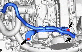
Slide the clamp and disconnect the union to check valve hose from the vacuum pump assembly.
Remove the 2 bolts and No. 2 hose to hose tube from the cylinder head cover sub-assembly and hose bracket.
12632
2.REMOVE NO. 2 ENGINE COVER BRACKET
82121
3.REMOVE ENGINE WIRE
17363K
4.REMOVE INTERCOOLER AIR TUBE
26100G
5.REMOVE DIESEL THROTTLE BODY ASSEMBLY
16278
6.REMOVE NO. 2 WATER BY-PASS PIPE
89481B
7.REMOVE DIFFERENTIAL PRESSURE SENSOR (w/ DPF)
89425
8.REMOVE EXHAUST GAS TEMPERATURE SENSOR (w/ DPF)
25733A
9.REMOVE NO. 1 VACUUM PIPE (w/ DPF)
25734
10.REMOVE NO. 2 VACUUM PIPE (w/ DPF)
17578B
11.REMOVE PIPE CLAMP (w/ DPF)
12631A
12.REMOVE ENGINE COVER BRACKET
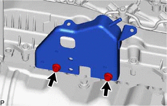
Remove the 2 bolts and engine cover bracket from the cylinder head sub-assembly.
23265C
13.REMOVE GAS FILTER
89421C
14.REMOVE DIESEL TURBO PRESSURE SENSOR
25625
15.REMOVE EGR VALVE BRACKET
25612
16.REMOVE NO. 2 EGR PIPE
16206B
17.REMOVE NO. 3 WATER BY-PASS PIPE SUB-ASSEMBLY
27148A
18.REMOVE CONNECTING WIRE
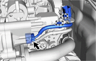
Disconnect the connector from the common rail assembly.
Detach the 2 clamps and remove the connecting wire from the hose bracket.
25601
19.REMOVE NO. 1 EGR PIPE SUB-ASSEMBLY
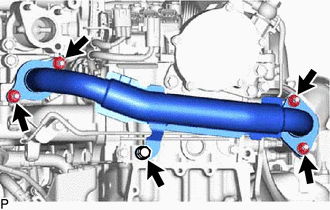
Remove the 4 nuts, bolt and No. 1 EGR pipe sub-assembly from the exhaust manifold, electric EGR control valve assembly and No. 1 vacuum transmitting pipe sub-assembly.
Remove the 2 gaskets from the exhaust manifold and electric EGR control valve assembly.
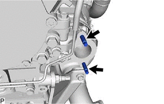
Using an E8 "TORX" socket wrench, remove the 2 stud bolts from the exhaust manifold.
25804
20.REMOVE VACUUM CONTROL VALVE SET
16209
21.REMOVE NO. 4 WATER BY-PASS PIPE SUB-ASSEMBLY
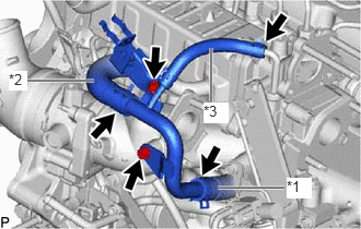
| *1 | No. 6 Water By-pass Hose |
| *2 | No. 7 Water By-pass Hose |
| *3 | Water Hose |
Slide the clamp and disconnect the No. 6 water by-pass hose from the No. 4 water by-pass pipe sub-assembly.
Slide the clamp and disconnect the No. 7 water by-pass hose from the No. 4 water by-pass pipe sub-assembly.
Slide the clamp and disconnect the water hose from the No. 2 EGR valve assembly.
Remove the 2 bolts and No. 4 water by-pass pipe sub-assembly from the intake manifold.
25800
22.REMOVE NO. 1 EGR COOLER AND NO. 2 EGR VALVE ASSEMBLY WITH ELECTRIC EGR CONTROL VALVE ASSEMBLY
11409
23.REMOVE ENGINE OIL LEVEL DIPSTICK GUIDE
23812D
24.REMOVE NO. 2 FUEL PIPE
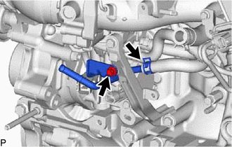
Slide the clamp and disconnect the No. 1 fuel hose from the No. 2 fuel pipe.
Remove the bolt and No. 2 fuel pipe from the manifold stay.
25.REMOVE WIRING HARNESS CLAMP BRACKET
17118
26.REMOVE MANIFOLD STAY
22803
27.REMOVE FUEL INJECTION PUMP COVER SUB-ASSEMBLY
23243B
28.REMOVE FUEL PUMP MOTOR WIRE
23273H
29.REMOVE NO. 2 FUEL HOSE
23271H
30.REMOVE NO. 1 FUEL HOSE
23804D
31.REMOVE NO. 4 FUEL PIPE SUB-ASSEMBLY (w/ DPF)
23815D
32.REMOVE NO. 3 FUEL PIPE (w/ DPF)
23804C
33.REMOVE FUEL INLET PIPE SUB-ASSEMBLY
23770
34.REMOVE NO. 2 NOZZLE LEAKAGE PIPE ASSEMBLY
17111
35.REMOVE INTAKE MANIFOLD
36.REMOVE WIRING HARNESS CLAMP BRACKET
23811H
37.REMOVE NO. 1 FUEL PIPE (w/ DPF)
23760
38.REMOVE NOZZLE LEAKAGE PIPE ASSEMBLY
39.REMOVE WIRING HARNESS CLAMP BRACKET
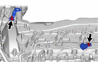
Remove the 2 bolts and 2 wiring harness clamp brackets from the cylinder head cover sub-assembly.
23701
40.REMOVE NO. 1 AND NO. 2 INJECTION PIPE SUB-ASSEMBLY
23810A
41.REMOVE COMMON RAIL ASSEMBLY
19871
42.REMOVE NO. 1 GLOW PLUG CONNECTOR
19850
43.REMOVE GLOW PLUG ASSEMBLY
44781
44.REMOVE HOSE BRACKET
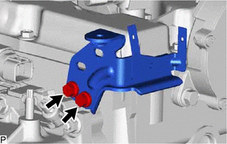
Remove the 2 bolts and hose bracket from the cylinder head sub-assembly.
23300D
45.REMOVE DIESEL FUEL FILTER ASSEMBLY (w/ DPF)
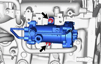
Remove the 2 nuts and diesel fuel filter assembly from the cylinder block sub-assembly.
23780
46.REMOVE NO. 3 NOZZLE LEAKAGE PIPE (w/o DPF)
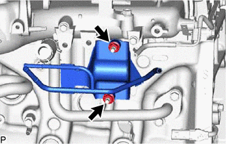
Remove the 2 nuts and No. 3 nozzle leakage pipe from the cylinder block sub-assembly.
16025
47.REMOVE NO. 5 WATER BY-PASS PIPE SUB-ASSEMBLY
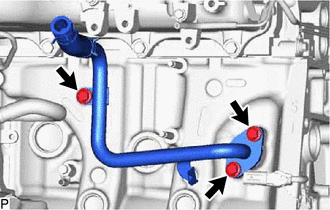
Remove the 3 bolts, No. 5 water by-pass pipe sub-assembly and gasket from the cylinder block sub-assembly.
88431
48.REMOVE NO. 1 COMPRESSOR MOUNTING BRACKET
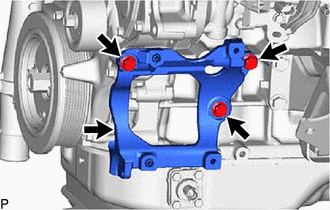
Remove the 4 bolts and No. 1 compressor mounting bracket from the cylinder block sub-assembly, timing chain case assembly and timing chain cover sub-assembly.
89422C
49.REMOVE ENGINE COOLANT TEMPERATURE SENSOR
16282
50.REMOVE NO. 5 WATER BY-PASS HOSE (w/ DPF)
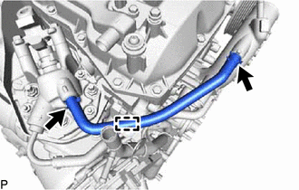
Slide the 2 clamps and disconnect the No. 5 water by-pass hose from the No. 1 injector holder and water outlet sub-assembly.
Detach the clamp and remove the No. 5 water by-pass hose from the No. 1 water hose clamp bracket.
16281
51.DISCONNECT NO. 4 WATER BY-PASS HOSE (w/ DPF)
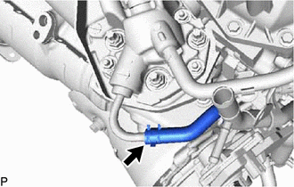
Slide the clamp and disconnect the No. 4 water by-pass hose from the No. 1 injector holder.
23295D
52.REMOVE NO. 1 INJECTOR HOLDER (w/ DPF)
17168
53.REMOVE NO. 2 EXHAUST MANIFOLD HEAT INSULATOR (w/ DPF)
89467B
54.REMOVE AIR FUEL RATIO SENSOR (w/ DPF)
17167
55.REMOVE NO. 1 EXHAUST MANIFOLD HEAT INSULATOR
17271
56.REMOVE NO. 1 TURBO INSULATOR
57.REMOVE NO. 2 EXHAUST PIPE SUPPORT STAY
58.REMOVE EXHAUST PIPE SUPPORT STAY
25051
59.REMOVE EXHAUST MANIFOLD CONVERTER SUB-ASSEMBLY
12261
60.REMOVE PCV HOSE
16279
61.REMOVE NO. 3 WATER BY-PASS PIPE
16268
62.REMOVE NO. 1 WATER BY-PASS PIPE
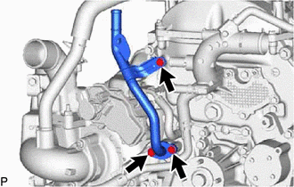
Remove the 3 bolts, No. 1 water by-pass pipe and gasket from the timing chain cover sub-assembly.
16284
63.DISCONNECT NO. 1 AND NO. 2 TURBO WATER HOSE
17293
64.REMOVE TURBOCHARGER STAY
15474
65.REMOVE TURBO OIL OUTLET PIPE
15407
66.REMOVE TURBO OIL INLET PIPE SUB-ASSEMBLY
17201
67.REMOVE TURBOCHARGER SUB-ASSEMBLY
17141
68.REMOVE EXHAUST MANIFOLD
83530
69.REMOVE ENGINE OIL PRESSURE SWITCH ASSEMBLY
16207
70.REMOVE NO. 2 WATER BY-PASS PIPE SUB-ASSEMBLY
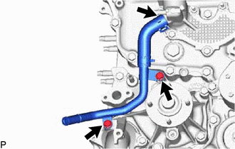
Slide the clamp and disconnect the No. 3 water by-pass hose from the water outlet sub-assembly.
Remove the 2 bolts and No. 2 water by-pass pipe sub-assembly from the engine water pump assembly and water inlet.
16304
71.REMOVE WATER OUTLET SUB-ASSEMBLY
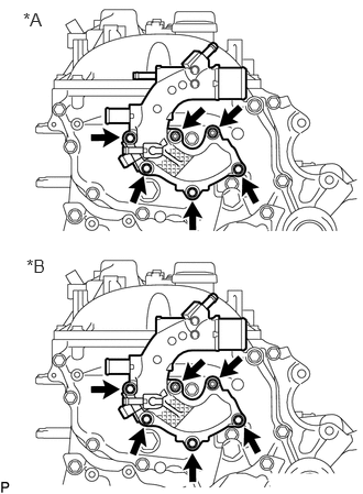
| *A | w/ DPF |
| *B | w/o DPF |
Remove the 4 bolts, 2 nuts and water outlet sub-assembly from the timing chain cover sub-assembly.
Remove the gasket from the timing chain cover sub-assembly.
16321
72.REMOVE WATER INLET
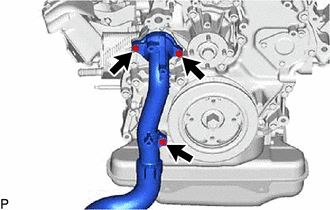
Remove the 3 bolts and water inlet from the timing chain cover sub-assembly.
16331A
73.REMOVE THERMOSTAT
16603
74.REMOVE NO. 1 IDLER PULLEY SUB-ASSEMBLY
16620
75.REMOVE V-RIBBED BELT TENSIONER ASSEMBLY
25706
76.REMOVE NO. 1 VACUUM TRANSMITTING PIPE SUB-ASSEMBLY
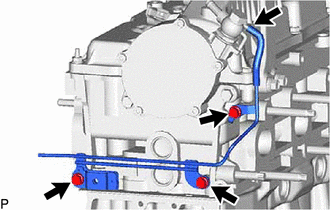
Disconnect the No. 1 vacuum transmitting hose from the vacuum pump assembly.
Remove the 3 bolts and No. 1 vacuum transmitting pipe sub-assembly from the cylinder head sub-assembly.
29300
77.REMOVE VACUUM PUMP ASSEMBLY
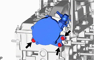
Remove the 3 bolts and vacuum pump assembly from the cylinder head sub-assembly.
Remove the 2 O-rings from the vacuum pump assembly.
11382C
78.REMOVE CAMSHAFT OIL SEAL RETAINER
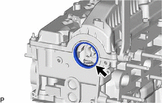
Remove the camshaft oil seal retainer from the No. 3 camshaft bearing cap and cylinder head sub-assembly.
13471
79.REMOVE CRANKSHAFT PULLEY
16575C
80.REMOVE NO. 1 WATER HOSE CLAMP BRACKET (w/ DPF)
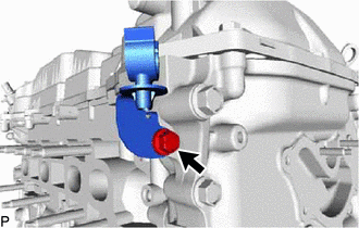
Remove the bolt and No. 1 water hose clamp bracket from the timing chain case assembly.