2TR-FE EMISSION CONTROL AIR PUMP(w/ Secondary Air Injection System) INSTALLATION
PROCEDURE

 17610C
1.INSTALL AIR PUMP ASSEMBLY
Attach the 3 fittings of the air pump insulators to install the air pump assembly to the air pump bracket.
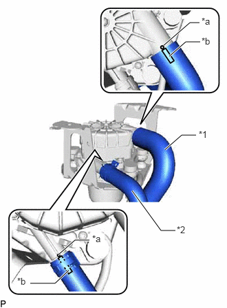
| *1 | No. 2 Air Injection System Hose |
| *2 | No. 3 Air Injection System Hose |
| *a | Rib |
| *b | Paint Mark |
Connect the No. 2 air injection system hose so that its paint mark aligns with the rib of the air pump assembly as shown in the illustration.
- HINT:
-
Make sure the paint mark of the No. 2 air injection system hose is facing upward.
Connect the No. 3 air injection system hose so that its paint mark aligns with the rib of the air pump assembly as shown in the illustration.
- HINT:
-
Make sure the paint mark of the No. 3 air injection system hose is facing upward.
Slide the clip to secure the No. 3 air injection system hose.
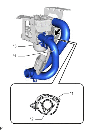
| *1 | No. 3 Air Injection System Hose |
| *2 | Wire Harness |
| *3 | Hose Clamp |
Install the hose clamp to the No. 3 air injection system hose and wire harness as shown in the illustration.
17611A
2.INSTALL AIR PUMP INLET PIPE
Install the air pump inlet pipe to the body panel with the 2 bolts.
- Torque:
- 6.0 N*m (61 kgf*cm, 53 in.*lbf)
17314C
3.INSTALL AIR PUMP ASSEMBLY WITH BRACKET
Install the air pump assembly with bracket to the body panel with the 3 bolts.
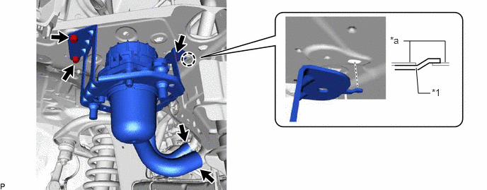
| *1 | Air Pump Bracket | - | - |
| *a | Body Panel | - | - |
- Torque:
- 8.0 N*m (82 kgf*cm, 71 in.*lbf)
- HINT:
-
Insert the protrusion of the air pump bracket into the hole in the body.
Connect the No. 3 air injection system hose to the air pump inlet pipe, and slide the clip to secure the hose.
Connect the No. 2 air injection system hose to the air pump inlet pipe.
Attach the clamp and connect the wire harness.
Connect the air pump connector.
17344
4.INSTALL NO. 4 AIR INJECTION SYSTEM HOSE
Connect the No. 4 air injection system hose to the air switching valve assembly and air pump inlet pipe, and slide the 2 clips to secure the hoses.
Install the hose clamp to the No. 4 air injection system hose and radiator hose inlet.
17621A
5.INSTALL AIR PUMP INLET
Install the air pump inlet to the No. 1 air injection system hose.
Install the No. 1 air injection system hose to the air pump inlet pipe.
Connect the air pump inlet with the bolt.
- Torque:
- 6.0 N*m (61 kgf*cm, 53 in.*lbf)
17701
6.INSTALL AIR CLEANER CASE SUB-ASSEMBLY
17801
7.INSTALL AIR CLEANER FILTER ELEMENT SUB-ASSEMBLY
17705
8.INSTALL AIR CLEANER CAP SUB-ASSEMBLY WITH NO. 1 AIR CLEANER HOSE
53875A
9.CONNECT FRONT FENDER LINER RH
Connect the front fender liner RH to the front bumper cover and body panel with the 6 clips and 3 screws.
53736
10.INSTALL FRONT UPPER FENDER APRON SEAL RH