2KD-FTV ENGINE MECHANICAL ENGINE UNIT DISASSEMBLY
CAUTION / NOTICE / HINT
- NOTICE:
- ·
When replacing the parts in the following chart (A), replace the No. 1 injection pipe sub-assembly, No. 2 injection pipe sub-assembly, No. 3 injection pipe sub-assembly, No. 4 injection pipe sub-assembly and/or fuel inlet pipe sub-assembly with new ones.
Replaced Parts (A) Pipes Requiring New Replacement ·Injector assembly (including shuffling the injector assemblies between the cylinders)
·Common rail assembly
·Cylinder head sub-assembly
·No. 1 injection pipe sub-assembly
·No. 2 injection pipe sub-assembly
·No. 3 injection pipe sub-assembly
·No. 4 injection pipe sub-assembly
·Supply pump assembly
·Common rail assembly
·Cylinder block sub-assembly
·Cylinder head sub-assembly
·Cylinder head gasket
·Timing Gear Case Assembly
Fuel inlet pipe sub-assembly
·After removing the No. 1 injection pipe sub-assembly, No. 2 injection pipe sub-assembly, No. 3 injection pipe sub-assembly, No. 4 injection pipe sub-assembly and fuel inlet pipe sub-assembly, clean them with a brush and compressed air.
PROCEDURE

 12108
1.REMOVE OIL FILLER CAP SUB-ASSEMBLY
11201
2.REMOVE CYLINDER HEAD COVER SUB-ASSEMBLY
23670
3.REMOVE INJECTOR ASSEMBLY
13523P
4.REMOVE CAMSHAFT TIMING PULLEY
11322B
5.REMOVE NO. 2 TIMING BELT COVER
12581C
6.REMOVE CYLINDER BLOCK INSULATOR
Remove the cylinder block insulator from the cylinder head sub-assembly.
7.REMOVE CAMSHAFT SUB-ASSEMBLY
13751
8.REMOVE VALVE LIFTER
Remove the valve lifters from the cylinder head sub-assembly.
- HINT:
-
Arrange the valve lifters in the correct order.
11101
9.REMOVE CYLINDER HEAD SUB-ASSEMBLY
11115
10.REMOVE CYLINDER HEAD GASKET
16100
11.REMOVE ENGINE WATER PUMP ASSEMBLY
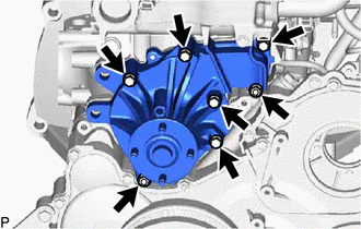
Remove the 5 bolts, 2 nuts, engine water pump assembly and gasket from the cylinder block sub-assembly.
12.REMOVE TIMING GEAR COVER
- NOTICE:
-
As the fuel supply pump assembly is not installed, the injection gear is loose inside the timing gear case assembly. Do not allow the injection gear to fall.
- HINT:
-
To prevent the injection gear from falling, temporarily install the fuel supply pump assembly.
Remove the bolt and No. 1 vacuum transmitting pipe.
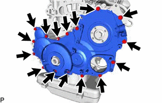
Remove the 14 bolts and 2 nuts.
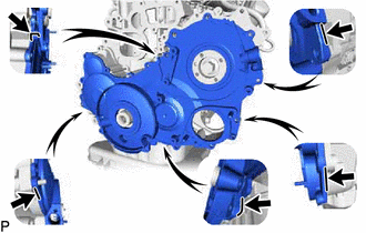
Pry the timing gear cover at the locations shown in the illustration and remove the timing gear cover.
- NOTICE:
-
Be careful not to drop the injection gear.
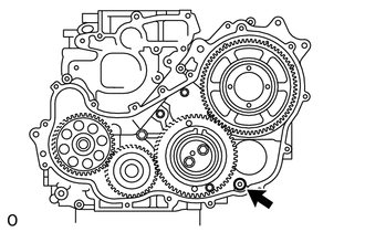
Remove the O-ring from the timing gear case assembly.
13613E
13.REMOVE INJECTION GEAR
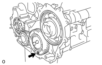
Secure the No. 2 idle sub gear to the No. 1 idle gear with a service bolt.
- Torque:
- 8.0 N*m (82 kgf*cm, 71 in.*lbf)
- NOTICE:
-
If the bolt hole of the No. 2 idle sub gear is not aligned with the bolt hole of the No. 1 idle gear, rotate the crankshaft counterclockwise to align the bolt holes. Then install the service bolt.
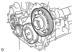
Remove the injection gear from the timing gear case assembly.
19315
14.REMOVE NO. 1 CRANKSHAFT POSITION SENSOR PLATE
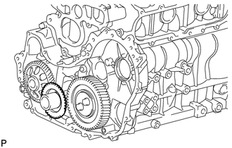
Remove the No. 1 crankshaft position sensor plate from the crankshaft.
15.INSPECT BACKLASH OF CRANKSHAFT TIMING GEAR TO OIL PUMP GEAR
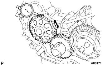
Using a dial indicator, measure the backlash.
- Standard gear backlash:
0.02 to 0.15 mm (0.000787 to 0.00591 in.)
- Maximum gear backlash:
0.2 mm (0.00787 in.)
If the gear backlash is more than the maximum, replace the crankshaft timing gear or timing gear case assembly.
16.INSPECT BACKLASH OF CRANKSHAFT TIMING GEAR TO NO. 1 IDLE GEAR
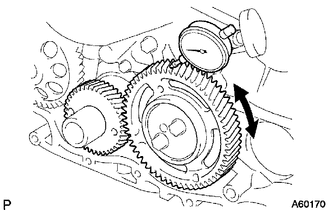
Using a dial indicator, measure the backlash.
- Standard gear backlash:
0.02 to 0.15 mm (0.000787 to 0.00591 in.)
- Maximum gear backlash:
0.2 mm (0.00787 in.)
If the gear backlash is more than the maximum, replace the crankshaft timing gear or No. 1 idle gear.
17.INSPECT NO. 1 IDLE GEAR THRUST CLEARANCE
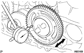
Using a dial indicator, measure the thrust clearance.
- Standard thrust clearance:
0.06 to 0.11 mm (0.00236 to 0.00433 in.)
- Maximum thrust clearance:
0.3 mm (0.0118 in.)
If the thrust clearance is more than the maximum, replace the idle gear thrust plate. If necessary, replace the No. 1 idle gear or No. 1 idle gear shaft.
13521
18.REMOVE CRANKSHAFT TIMING GEAR
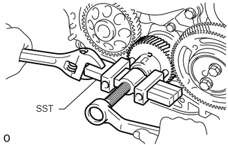
Using SST, remove the crankshaft timing gear from the crankshaft.
- SST
- 09950-50013 (09951-05010, 09952-05010, 09953-05010, 09954-05021)
19.INSPECT BACKLASH OF INJECTION GEAR TO NO. 1 IDLE GEAR
Install the fuel supply pump assembly with the 2 nuts.
- Torque:
- 21 N*m (214 kgf*cm, 15 ft.*lbf)
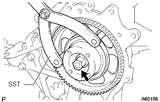
Using SST, install the injection gear with the nut.
- SST
- 09960-10010 (09962-01000, 09963-01000)
- Torque:
- 63.7 N*m (650 kgf*cm, 47 ft.*lbf)
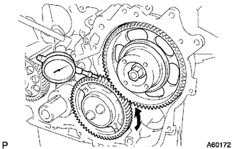
Using a dial indicator, measure the backlash.
- Standard gear backlash:
0.02 to 0.15 mm (0.000787 to 0.00591 in.)
- Maximum gear backlash:
0.2 mm (0.00787 in.)
If the gear backlash is more than the maximum, replace the injection gear or No. 1 idle gear.
Using SST, remove the nut and injection gear.
- SST
- 09960-10010 (09962-01000, 09963-01000)
Remove the 2 nuts and fuel supply pump assembly.
13572
20.REMOVE IDLE GEAR THRUST PLATE
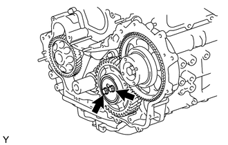
Remove the 2 bolts and idle gear thrust plate from the No. 1 idle gear shaft.
13525
21.REMOVE NO. 1 IDLE GEAR
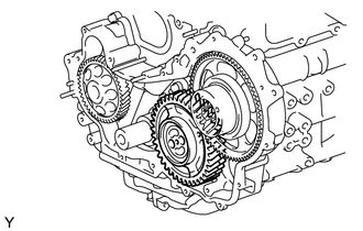
Remove the No. 1 idle gear together with the No. 2 idle sub gear from the No. 1 idle gear shaft.
13538
22.REMOVE NO. 2 IDLE SUB GEAR
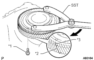
| *1 | Service Bolt |
| *2 | No. 1 Idle Gear |
| *3 | No. 2 Idle Sub Gear |

|
Turn |
Using SST, turn the No. 2 idle sub gear clockwise and remove the service bolt.
- SST
- 09960-10010 (09962-01000, 09963-00700)
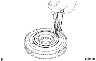
Using snap ring pliers, remove the snap ring.
Remove the wave washer, No. 2 idle sub gear and gear spring.
13581
23.REMOVE NO. 1 IDLE GEAR SHAFT
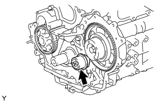
Remove the No. 1 idle gear shaft from the timing gear case assembly.
12101
24.REMOVE OIL PAN SUB-ASSEMBLY
Remove the 22 bolts and 2 nuts.
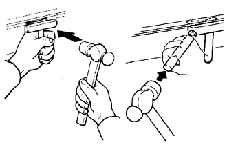
Insert the blade of an oil pan seal cutter between the oil pan sub-assembly and cylinder block sub-assembly, cut through the applied sealer and remove the oil pan sub-assembly from the cylinder block sub-assembly.
- NOTICE:
- ·
Do not use the oil pan seal cutter for the area between the oil pan sub-assembly and timing gear case assembly, or for the area between the oil pan sub-assembly and rear oil seal retainer.
·Be careful not to damage the oil pan sub-assembly flange.
15104
25.REMOVE OIL STRAINER SUB-ASSEMBLY
Remove the 2 bolts, 2 nuts, oil strainer sub-assembly and gasket from the cylinder block sub-assembly.
11320
26.REMOVE TIMING GEAR CASE ASSEMBLY
Remove the bolt and No. 1 vacuum transmitting pipe.
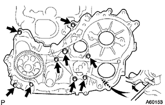
Remove the union bolt and 8 bolts.
Pry the timing gear case assembly at the location shown in the illustration and remove the timing gear case assembly and gasket from the cylinder block sub-assembly.
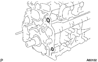
Remove the 2 O-rings from the cylinder block sub-assembly.
11381
27.REMOVE REAR ENGINE OIL SEAL RETAINER
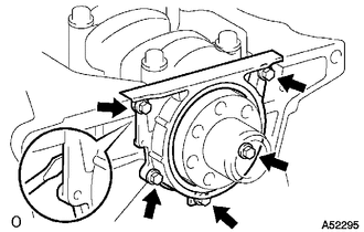
Remove the 5 bolts.
Using a screwdriver, remove the rear engine oil seal retainer by prying between the rear engine oil seal retainer and cylinder block sub-assembly.
11381A
28.REMOVE REAR ENGINE OIL SEAL
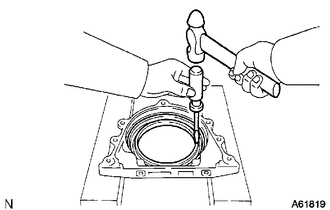
Using a screwdriver and hammer, tap out the rear engine oil seal from the rear engine oil seal retainer.
11303A
29.REMOVE FRONT CRANKSHAFT OIL SEAL
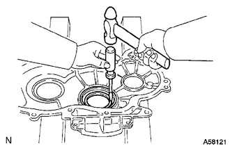
Using a screwdriver and hammer, tap out the front crankshaft oil seal from the timing gear cover.
11301Q
30.REMOVE INJECTION PUMP OIL SEAL
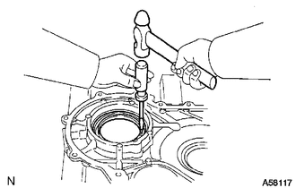
Using a screwdriver and hammer, tap out the injection pump oil seal from the timing gear cover.