INTERIOR PANELS / TRIM FRONT CONSOLE BOX REMOVAL
CAUTION / NOTICE / HINT
- HINT:
- ·
Use the same procedure for RHD and LHD vehicles.
·The procedure listed below is for RHD vehicles
PROCEDURE

 55667
1.REMOVE INSTRUMENT PANEL REGISTER BEZEL GARNISH
55011A
2.REMOVE NO. 1 INSTRUMENT PANEL GARNISH SUB-ASSEMBLY
55012A
3.REMOVE NO. 2 INSTRUMENT PANEL GARNISH SUB-ASSEMBLY
33504F
4.REMOVE SHIFT LEVER KNOB SUB-ASSEMBLY
for Automatic Transmission:
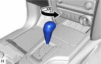

|
Remove in this Direction |
Twist the shift lever knob sub-assembly as shown in the illustration and remove it.
for Manual Transmission:
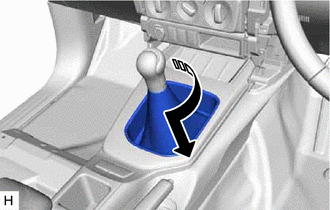
|
|
Remove in this Direction |
Twist the shifting hole cover as shown in the illustration and disconnect it.
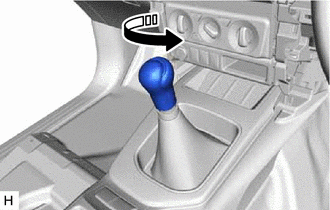
|
|
Remove in this Direction |
Twist the shift lever knob sub-assembly as shown in the illustration and remove it.
58808
5.REMOVE SHIFTING HOLE COVER SUB-ASSEMBLY (for Automatic Transmission)
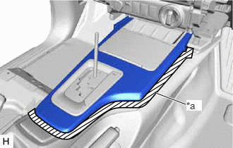
| *a | Protective Tape |
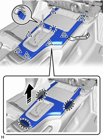
Put protective tape around the shifting hole cover sub-assembly.

|
Insert Moulding Remover B Here |
|
|
Remove in this Direction |
Insert moulding remover B at the position shown in the illustration and pull as shown to detach the claw and clip and remove the shifting hole cover sub-assembly.
58804A
6.REMOVE UPPER CONSOLE PANEL SUB-ASSEMBLY
for Automatic Transmission:
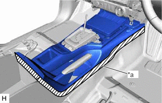
| *a | Protective Tape |
Put protective tape around the upper console panel sub-assembly.
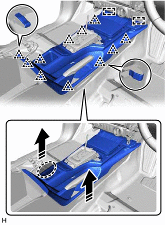
|
|
Place Hands Here |
|
|
Remove in this Direction |
Place your hands at the position shown in the illustration and pull as shown to detach the clip and guide.
Disconnect the connector.
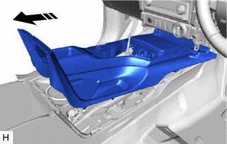
|
|
Remove in this Direction |
Pull as shown in the illustration to remove the upper console panel sub-assembly.
for Manual Transmission:
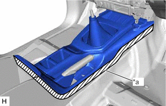
| *a | Protective Tape |
Put protective tape around the upper console panel sub-assembly.
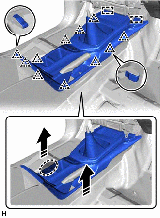
|
|
Place Hands Here |
|
|
Remove in this Direction |
Place your hands at the position shown in the illustration and pull as shown to detach the clip and guide.
Disconnect the connector.
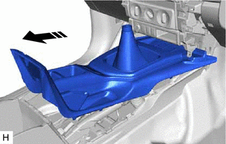
|
|
Remove in this Direction |
Pull as shown in the illustration to remove the upper console panel sub-assembly.
58916
7.REMOVE BOX BOTTOM MAT
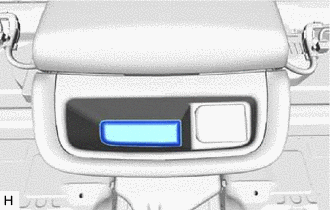
Remove the box bottom mat.
58903A
8.REMOVE REAR CONSOLE END PANEL SUB-ASSEMBLY
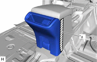
| *a | Protective Tape |
Put protective tape around the rear console end panel sub-assembly.
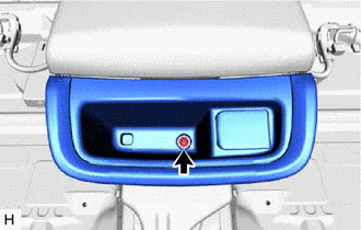
Remove the screw.
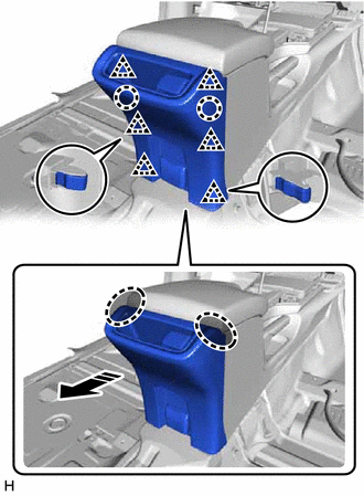
|
|
Place Hands Here |
|
|
Remove in this Direction |
Place your hands at the position shown in the illustration and pull as shown to detach the clip and claw.
Disconnect the connector and remove the rear console end panel sub-assembly.
58815B
9.REMOVE CONSOLE BOX CARPET
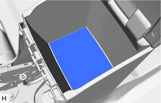
Remove the console box carpet.
58810J
10.REMOVE CONSOLE BOX ASSEMBLY
for Automatic Transmission:
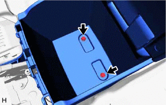
Remove the 2 bolts.
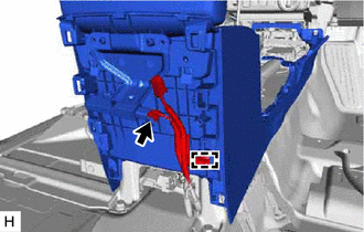
Disconnect the connector and detach the clamp.
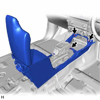
Remove the 3 screws.
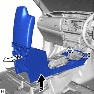
|
|
Remove in this Direction (1) |

|
Remove in this Direction (2) |
Pull as shown in the illustration to remove the console box assembly.
for Manual Transmission:
Remove the 2 bolts.
Disconnect the connector and detach the clamp.
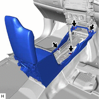
Remove the 4 screws.
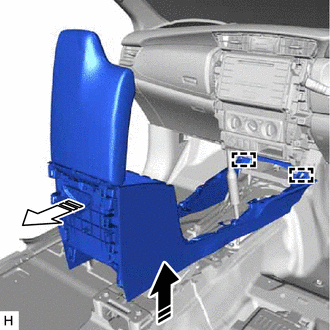
|
|
Remove in this Direction (1) |
|
|
Remove in this Direction (2) |
Pull as shown in the illustration to remove the console box assembly.