EXTERIOR PANELS / TRIM BLACK OUT TAPE(for Rear Door) INSTALLATION
CAUTION / NOTICE / HINT
- HINT:
- ·
Use the same procedure for the RH and LH sides.
·The procedure listed below is for the LH side.
·Use the same procedure for RHD and LHD vehicles.
·The procedure listed below are for RHD vehicles.
PROCEDURE

 1. REPAIR INSTRUCTION
75926C
2.INSTALL NO. 3 BLACK OUT TAPE LH
- HINT:
-
When installing the No. 3 black out tape LH, heat the rear door panel and No. 3 black out tape LH using a heat light.
- Standard:
Item Temperature Rear Door Panel 40 to 60°C (104 to 140°F) No. 3 Black Out Tape LH 20 to 30°C (68 to 86°F)
- CAUTION:
-
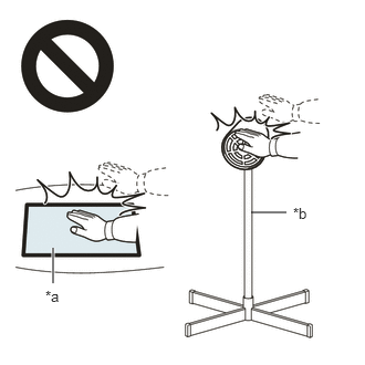 2.365,2 2.698,2 false 0.5,2.333 0.5,2.667 true 0.427,2.708 0.74,2.865 0.313,0.156 10 false *a 2.76,1.927 3.073,2.083 0.313,0.156 10 false *b
*a Heated Part *b Heat Light
- ·
Do not touch the heat light and heated parts.
·Touching the heat light may result in burns.
·Touching heated parts for a long time may result in burns.
Refer to the illustration to position a new No. 3 black out tape LH.
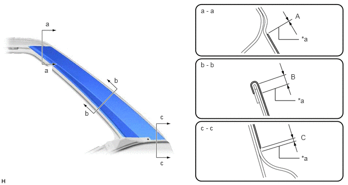
| *a | Edge of Curved Surface | - | - |
- Standard:
Area Specified Condition Area Specified Condition A -1.0 to 1.0 mm (-0.0394 to 0.0394 in.) B 3.0 mm (0.118 in.) C 0 to 2.0 mm (0 to 0.0787 in.) - -
Remove the release paper from the No. 3 black out tape LH.
After installing the No. 3 black out tape LH, remove the unnecessary part above the perforation.
75924C
3.INSTALL NO. 2 BLACK OUT TAPE LH
- HINT:
-
When installing the No. 2 black out tape LH, heat the rear door panel and No. 2 black out tape LH using a heat light.
- Standard:
Item Temperature Rear Door Panel 40 to 60°C (104 to 140°F) No. 2 Black Out Tape LH 20 to 30°C (68 to 86°F)
- CAUTION:
-
2.365,2 2.698,2 false 0.5,2.333 0.5,2.667 true 0.427,2.708 0.74,2.865 0.313,0.156 10 false *a 2.76,1.927 3.073,2.083 0.313,0.156 10 false *b
*a Heated Part *b Heat Light
- ·
Do not touch the heat light and heated parts.
·Touching the heat light may result in burns.
·Touching heated parts for a long time may result in burns.
Refer to the illustration to position a new No. 2 black out tape LH.
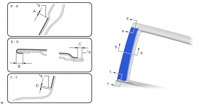
| *a | Edge of Curved Surface | - | - |
- Standard:
Area Specified Condition Area Specified Condition A -1.0 to 1.0 mm (-0.0394 to 0.0394 in.) B 3.0 to 5.0 mm (0.118 to 0.197 in.) C 3.0 mm (0.118 in.) D 0 to 2.0 mm (0 to 0.0787 in.)
Remove the release paper from the No. 2 black out tape LH.
After installing the No. 2 black out tape LH, remove the unnecessary part above the perforation.
67872
4.INSTALL REAR DOOR WEATHERSTRIP LH
- HINT:
-
Use the same procedure described for the RH side.
-
Click hereVehicle Exterior>DOOR / HATCH>REAR DOOR>REASSEMBLY
75740
5.INSTALL REAR DOOR BELT MOULDING ASSEMBLY LH
75724
6.INSTALL REAR DOOR REAR BELT MOULDING LH
68124C
7.INSTALL REAR DOOR QUARTER WINDOW GLASS LH
- HINT:
-
Use the same procedure described for the RH side.
-
Click hereVehicle Exterior>DOOR / HATCH>REAR DOOR>REASSEMBLY
68104
8.INSTALL REAR DOOR GLASS SUB-ASSEMBLY LH
- HINT:
-
Use the same procedure described for the RH side.
-
Click hereVehicle Exterior>DOOR / HATCH>REAR DOOR>REASSEMBLY
67408E
9.INSTALL REAR DOOR WINDOW DIVISION BAR SUB-ASSEMBLY LH
- HINT:
-
Use the same procedure described for the RH side.
-
Click hereVehicle Exterior>DOOR / HATCH>REAR DOOR>REASSEMBLY
68152C
10.INSTALL REAR DOOR GLASS RUN LH
- HINT:
-
Use the same procedure described for the RH side.
-
Click hereVehicle Exterior>DOOR / HATCH>REAR DOOR>REASSEMBLY
67842E
11.INSTALL REAR DOOR SERVICE HOLE COVER LH
- HINT:
-
Use the same procedure described for the RH side.
-
Click hereVehicle Exterior>DOOR / HATCH>REAR DOOR>REASSEMBLY
67604
12.INSTALL REAR DOOR TRIM BOARD SUB-ASSEMBLY LH
- HINT:
-
Use the same procedure described for the RH side.
-
Click hereVehicle Exterior>DOOR / HATCH>REAR DOOR>REASSEMBLY
69284D
13.INSTALL REAR DOOR INSIDE HANDLE BEZEL PLUG LH
- HINT:
-
Use the same procedure described for the RH side.
-
Click hereVehicle Exterior>DOOR / HATCH>REAR DOOR>REASSEMBLY
81230
14.INSTALL COURTESY LIGHT ASSEMBLY (w/ Courtesy Light)
15.INSTALL REAR POWER WINDOW REGULATOR SWITCH ASSEMBLY WITH REAR DOOR ARMREST BASE PANEL
- HINT:
-
Use the same procedure described for the RH side.
-
Click hereVehicle Exterior>DOOR / HATCH>REAR DOOR>REASSEMBLY
74260
16.INSTALL REAR ARMREST ASSEMBLY LH
- HINT:
-
Use the same procedure described for the RH side.
-
Click hereVehicle Exterior>DOOR / HATCH>REAR DOOR>REASSEMBLY
67674A
17.INSTALL REAR DOOR FRAME GARNISH LH
- HINT:
-
Use the same procedure described for the RH side.
-
Click hereVehicle Exterior>DOOR / HATCH>REAR DOOR>REASSEMBLY
18.CONNECT CABLE TO NEGATIVE BATTERY TERMINAL
- NOTICE:
-
When disconnecting the cable, some systems need to be initialized after the cable is reconnected.
-
Click hereGeneral>INTRODUCTION>REPAIR INSTRUCTION>INITIALIZATION