SEAT FRONT SEAT ASSEMBLY(for Manual Seat) REASSEMBLY
CAUTION / NOTICE / HINT
- CAUTION:
- ·
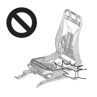
Wear protective gloves. Sharp areas on the parts may injure your hands.
·There is risk of injury.
- HINT:
- ·
Use the same procedure for RHD and LHD vehicles.
·The procedures listed below are for RHD vehicles.
·Use the same procedure for the RH and LH sides.
·The procedure listed below is for the RH side.
PROCEDURE

 72201A
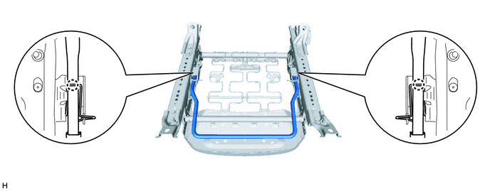
1.INSTALL SEAT TRACK HANDLE SUB-ASSEMBLY RH
Attach the claw and install the seat track handle sub-assembly RH.
71051A
2.INSTALL FRONT SEAT CUSHION SPRING SUB-ASSEMBLY RH
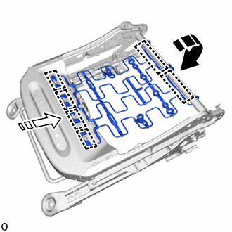

|
Install in this Direction (1) |

|
Install in this Direction (2) |
While rotating the part in the installation direction (1) shown in the illustration, attach the hook.
Push in the installation direction (2) shown in the illustration to attach the hook and install the front seat cushion spring sub-assembly RH.
71537G
3.INSTALL FRONT SEAT CUSHION EDGE PROTECTOR RH
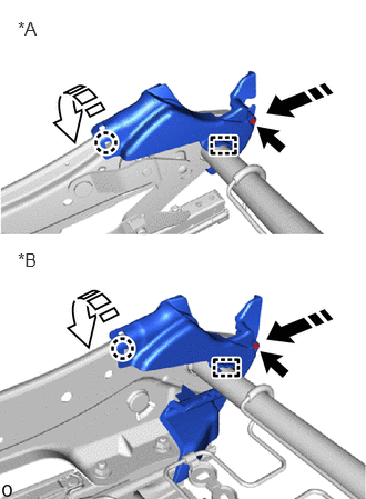
| *A | for Driver Side |
| *B | for Front Passenger Side |
|
|
Install in this Direction (1) |
|
|
Install in this Direction (2) |
Push in the installation direction (1) shown in the illustration to install the guide.
While expanding the part in the installation direction (2) shown in the illustration, attach the claw.
Install the front seat cushion edge protector RH with the screw.
71538A
4.INSTALL FRONT SEAT CUSHION EDGE PROTECTOR LH
- HINT:
-
Use the same procedure as for the RH side.
71873
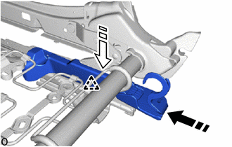
5.INSTALL FRONT SEAT LOWER CUSHION SHIELD RH (for Driver Side)
|
|
Install in this Direction (1) |
|
|
Install in this Direction (2) |
Push in the installation direction (1) shown in the illustration to temporarily install the front seat lower cushion shield RH.
Push in the installation direction (2) shown in the illustration to attach the clip.
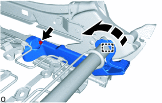
|
|
Install in this Direction |
Push in the guide in the installation direction shown in the illustration.
Install the front seat lower cushion shield RH with the screw.
71874
6.INSTALL FRONT SEAT LOWER CUSHION SHIELD LH (for Driver Side)
- HINT:
-
Use the same procedure as for the RH side.
7.INSTALL SEAT COVER WIRE
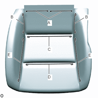
Install the seat cover wire.
- HINT:
- ·
There are service parts available for wires of 1000 mm (3.28 ft.) or longer and formed wires.
- ·
When a wire that is less than 1000 mm (3.28 ft.) in length is needed, cut and shape a 1000 mm (3.28 ft.) supplied wire into the dimensions shown in the illustration.
- ·
Refer to the precautions when creating a wire.
Click hereVehicle Interior>SEAT>FRONT SEAT ASSEMBLY(for Manual Seat)>PRECAUTION
- Length:
A 170 mm (6.70 in.) B 150 mm (5.91 in.) C 230 mm (9.06 in.) D 270 mm (10.63 in.) E 290 mm (11.42 in.)
- HINT:
-
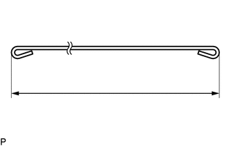
-
The dimensions shown in the illustration are the length.
71071S
8.INSTALL SEPARATE TYPE FRONT SEAT CUSHION COVER
- HINT:
- ·
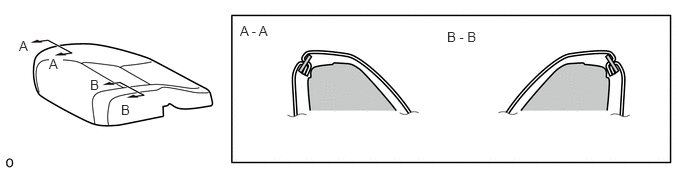
Refer to the precautions on wrinkles to avoid creating any on the separate type front seat cushion cover when installing the seat cover.
Click hereVehicle Interior>SEAT>FRONT SEAT ASSEMBLY(for Manual Seat)>PRECAUTION
- ·
As shown in the illustration, fix all of the cover seam allowances in the same direction.
 2.5,0.24 3.271,0.438 0.771,0.198 10 false A - A 4.656,0.302 5.427,0.5 0.771,0.198 10 false B - B 0.198,0.396 0.354,0.594 0.156,0.198 10 false A 0.51,0.583 0.656,0.75 0.146,0.167 10 true A 0.938,0.802 1.094,1 0.156,0.198 10 false B 1.26,1.063 1.656,1.406 0.396,0.344 10 false B
Temporarily install the separate type front seat cushion cover to the separate type front seat cushion pad.
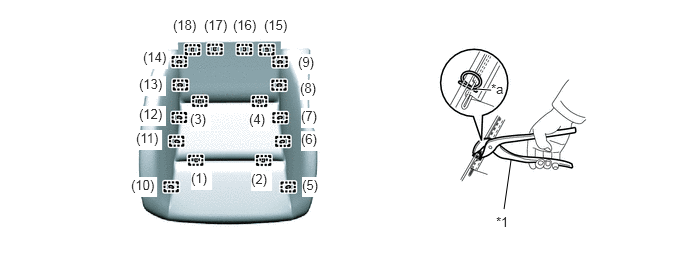
Using hog ring pliers, install the separate type front seat cushion cover to the separate type front seat cushion pad with 18 new hog rings in the order shown in the illustration.
| *1 | Hog Ring Pliers | - | - |
| *a | Cutout | - | - |
- NOTICE:
- ·
Do not dirty or damage the separate type front seat cushion cover.
- ·
Securely tighten the hog rings as shown in the illustration while making sure wrinkles do not form in the center of the fabric and separate type front seat cushion pad.
- HINT:
-
Install the hog rings at the cutouts if they are there.
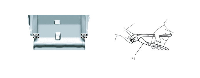
Using hog ring pliers, connect the 2 straps of the separate type front seat cushion cover to the separate type front seat cushion pad with 2 new hog rings.
| *1 | Hog Ring Pliers | - | - |
- NOTICE:
- ·
Do not dirty or damage the separate type front seat cushion cover.
- ·
Securely tighten the hog rings as shown in the illustration while making sure wrinkles do not form in the center of the fabric and separate type front seat cushion pad.
9.INSTALL SEAT CUSHION COVER WITH PAD
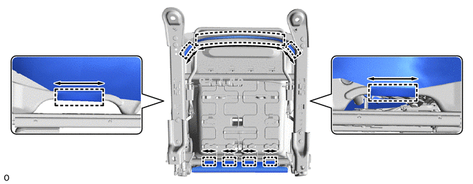
While sliding the part in the direction indicated by the arrow shown in the illustration, align the J hook to attach the seat cushion cover with pad.
71587B
10.INSTALL FRONT SEATBACK EDGE PROTECTOR
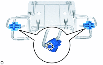
Attach the claw to install the 2 front seatback edge protectors.
71053S
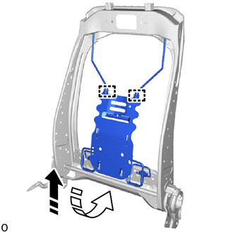
11.INSTALL FRONT SEATBACK SPRING SUB-ASSEMBLY RH
|
|
Install in this Direction (1) |
|
|
Install in this Direction (2) |
Temporarily install the 2 front No. 2 seatback hooks to the front seatback spring sub-assembly RH.
Push in the installation direction (1) shown in the illustration to install the front seatback spring sub-assembly RH.
Push in the installation direction (2) shown in the illustration to temporarily the front seatback spring sub-assembly RH.
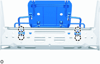
Attach the claw and install the 2 front seatback edge protectors.
71759D
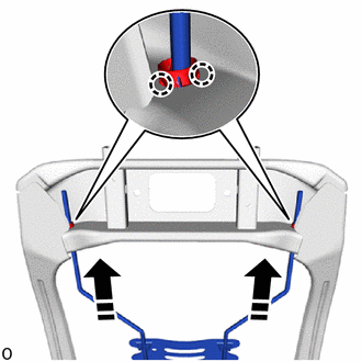
12.INSTALL FRONT NO. 2 SEATBACK HOOK
|
|
Install in this Direction |
Push in the installation direction shown in the illustration to attach the claw and install the 2 front No. 2 seatback hooks.
71759B
13.INSTALL FRONT SEATBACK HOOK
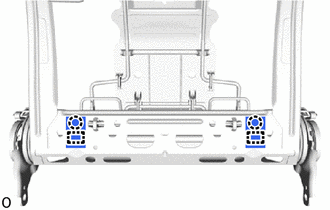
Attach the claw and hook to install the 2 front seatback hooks.
73910A
14.INSTALL FRONT SEAT AIRBAG ASSEMBLY RH (w/ Front Seat Side Airbag)
15.INSTALL SEAT COVER WIRE
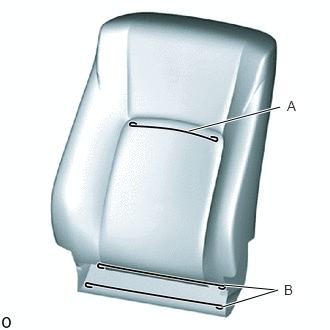
Install the seat cover wire.
- HINT:
- ·
There are service parts available for wires of 1000 mm (3.28 ft.) or longer and formed wires.
- ·
When a wire that is less than 1000 mm (3.28 ft.) in length is needed, cut and shape a 1000 mm (3.28 ft.) supplied wire into the dimensions shown in the illustration.
- ·
Refer to the precautions when creating a wire.
Click hereVehicle Interior>SEAT>FRONT SEAT ASSEMBLY(for Manual Seat)>PRECAUTION
- Length:
A 290 mm (11.42 in.) B 420 mm (1.38 ft.)
- HINT:
-
-
The dimensions shown in the illustration are the length.
71073S
16.INSTALL SEPARATE TYPE FRONT SEATBACK COVER
- HINT:
- ·
Refer to the precautions on wrinkles to avoid creating any on the separate type front seatback cover when installing the seat cover.
Click hereVehicle Interior>SEAT>FRONT SEAT ASSEMBLY(for Manual Seat)>PRECAUTION
- ·
As shown in the illustration, fix all of the cover seam allowances in the same direction.
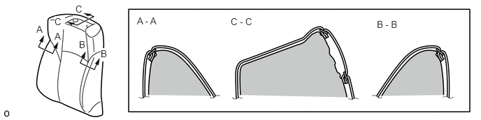 0.542,0.354 0.698,0.552 0.156,0.198 10 false A 0.813,0.458 0.969,0.656 0.156,0.198 10 false A 1.177,0.583 1.333,0.781 0.156,0.198 10 false B 1.5,0.719 1.656,0.917 0.156,0.198 10 true B 1.125,0.052 1.281,0.25 0.156,0.198 10 false C 0.813,0.24 0.969,0.438 0.156,0.198 10 true C 2.042,0.229 2.813,0.427 0.771,0.198 10 false A - A 3.438,0.24 4.208,0.438 0.771,0.198 10 false C - C 5.615,0.281 6.385,0.479 0.771,0.198 10 false B - B
Set the separate type front seatback cover.
Using hog ring pliers, install the separate type front seatback cover with 6 new hog rings in the order shown in the illustration.
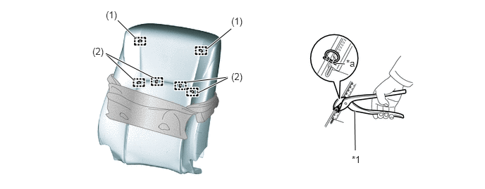
| *1 | Hog Ring Pliers | - | - |
| *a | Cutout | - | - |
- NOTICE:
- ·
Do not dirty or damage the separate type front seatback cover.
- ·
Securely tighten the hog rings as shown in the illustration while making sure wrinkles do not form in the center of the fabric and separate type front seatback pad.
- HINT:
-
Install the hog rings at the cutouts if they are there.
17.INSTALL SEATBACK COVER WITH PAD
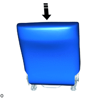
|
|
Install in this Direction |
Push in the installation direction shown in the illustration to temporarily install the seatback cover with pad.
w/ Front Seat Side Airbag:
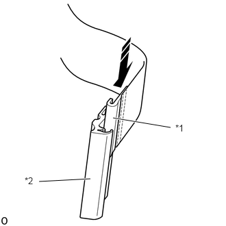
| *1 | J Hook A |
| *2 | J Hook B |
|
|
Install in this Direction |
Push in the installation direction shown in the illustration to attach the J hook A and J hook B.
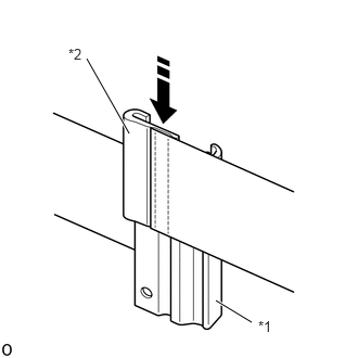
| *1 | J Hook B (J Hook A and J Hook B) |
| *2 | J Hook C |
|
|
Install in this Direction |
Push in the installation direction shown in the illustration to attach the J hook B (J hook A and J hook B) and J hook C.
Install a new rivet to J hook B.
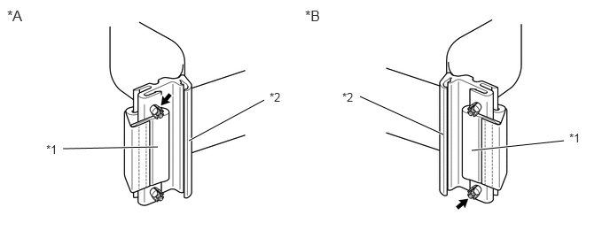
| *A | for LH seat | *B | for RH seat |
| *1 | J Hook A | *2 | J Hook B |
Place your hand at the position shown in the illustration and push in the installation direction to attach the J hook B.
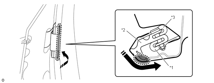
| *1 | J Hook A | *2 | J Hook B |
| *3 | J Hook C | - | - |

|
Place Hand Here |
|
Install in this Direction |
71931
18.INSTALL FRONT SEAT HEADREST SUPPORT
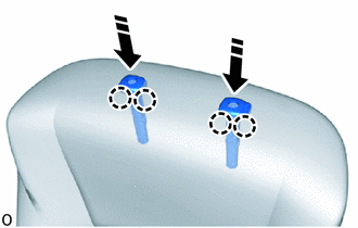
|
|
Install in this Direction |
Push in the installation direction shown in the illustration to attach the claw and install the 2 front seat headrest supports.
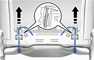
|
|
Install in this Direction |
Pull in the installation direction shown in the illustration to attach the guide to the 2 straps.
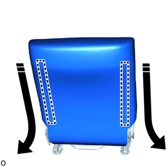
|
|
Install in this Direction |
Close the fasteners as shown in the illustration.
Using hog ring pliers, install 6 new hog rings.
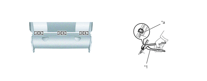
| *1 | Hog Ring Pliers | - | - |
| *a | Cutout | - | - |
- NOTICE:
- ·
Do not dirty or damage the separate type front seatback cover.
- ·
Securely tighten the hog rings as shown in the illustration while making sure wrinkles do not form in the center of the fabric and separate type front seatback pad.
- HINT:
-
Install the hog rings at the cutouts if they are there.
71759C
19.INSTALL FRONT NO. 1 SEATBACK HOOK
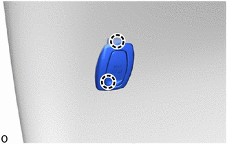
Attach the claw and install the front No. 1 seatback hook.
71875E
20.INSTALL RECLINING ADJUSTER INSIDE COVER RH
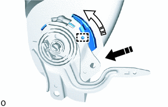
|
|
Install in this Direction (1) |
|
|
Install in this Direction (2) |
Push down in the installation direction (1) shown in the illustration.
Rotate the part in the installation direction (2) shown in the illustration and align the guide to install the reclining adjuster inside cover RH.
71876F
21.INSTALL RECLINING ADJUSTER INSIDE COVER LH
- HINT:
-
Use the same procedure as for the RH side.
71013S
22.INSTALL FRONT SEATBACK FRAME SUB-ASSEMBLY RH
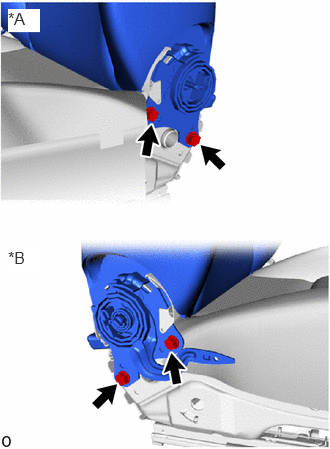
| *A | LH Side |
| *B | RH Side |
Install the 4 bolts and front seatback frame sub-assembly RH.
- Torque:
- 42 N*m (428 kgf*cm, 31 ft.*lbf)
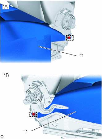
| *A | LH Side |
| *B | RH Side |
| *1 | Separate Type Front Seat Cushion Cover |
Attach the 2 hooks.
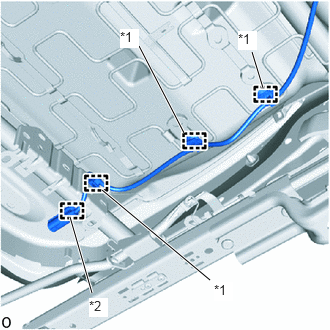
| *1 | Wire Harness Clamp |
| *2 | Connector Clamp |
w/ Front Seat Side Airbag:
Attach the wire harness clamp and connector clamp.
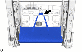
Install the band in the position shown in the illustration.
73230
23.INSTALL FRONT SEAT INNER BELT ASSEMBLY RH
71861
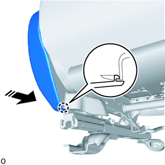
24.INSTALL FRONT SEAT INNER CUSHION SHIELD RH (for Driver Side)
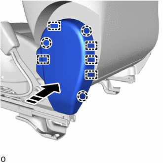
|
|
Install in this Direction |
Push in the installation direction shown in the illustration to attach the claw and guide.
|
|
Install in this Direction |
Push in installation direction shown in the illustration and attach the claw to install the front seat inner cushion shield RH.
71862
25.INSTALL FRONT SEAT INNER CUSHION SHIELD LH (for Front Passenger Side)
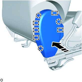
|
|
Install in this Direction |
Push in the installation direction shown in the illustration to attach the claw and guide.
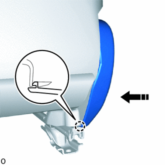
|
|
Install in this Direction |
Push in the installation direction shown in the illustration and attach the claw to install the front seat inner cushion shield LH.
71811D
26.INSTALL FRONT SEAT CUSHION SHIELD RH (for Driver Side)
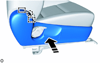
|
|
Install in this Direction |
Push in the installation direction shown in the illustration to attach the claw and guide.
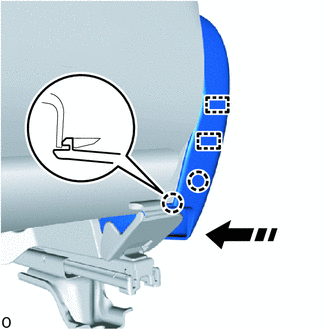
|
|
Install in this Direction |
Push in the installation direction shown in the illustration to attach the claw and guide.
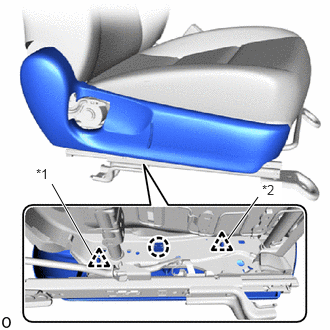
| *1 | Clip A |
| *2 | Clip B |
Attach the clip B.
Attach the claw.
Attach the clip A and install the front seat cushion shield RH.
71812D
27.INSTALL FRONT SEAT CUSHION SHIELD LH (for Front Passenger Side)
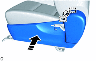
|
|
Install in this Direction |
Push in the installation direction shown in the illustration to attach the claw and guide.
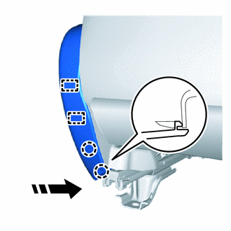
|
|
Install in this Direction |
Push in the installation direction shown in the illustration to attach the claw and guide.
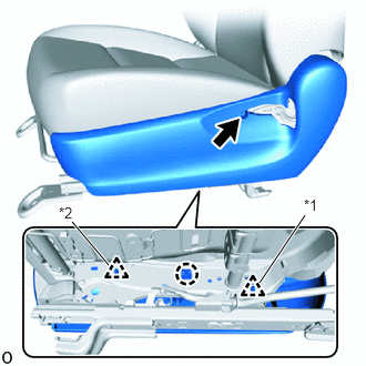
| *1 | Clip A |
| *2 | Clip B |
Attach clip B.
Attach the claw.
Attach clip A.
Install the front seat cushion shield LH with the screw.
72494
28.INSTALL VERTICAL ADJUSTING HANDLE RH (for Driver Side)
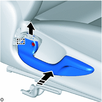
|
|
Install in this Direction |
With the reclining adjuster release handle RH pulled up.
Attach the guide, and then push in the installation direction shown in the illustration to install the vertical adjusting handle RH.
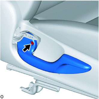
Install the screw.
72525A
29.INSTALL RECLINING ADJUSTER RELEASE HANDLE RH (for Driver Side)
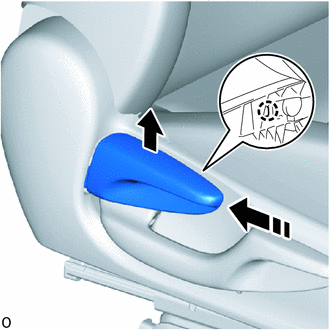
|
|
Install in this Direction |
With the reclining adjuster release handle RH pulled up.
Push in the installation direction shown in the illustration and attach the claw to install the reclining adjuster release handle RH.
72526E
30.INSTALL RECLINING ADJUSTER RELEASE HANDLE LH (for Front Passenger Side)
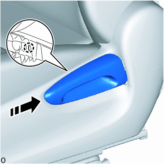
|
|
Install in this Direction |
Push in the installation direction shown in the illustration and attach the claw to install the reclining adjuster release handle LH.
71848A
31.INSTALL SEAT ADJUSTER COVER CAP RH
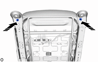
|
|
Install in this Direction |
Push in installation direction shown in the illustration to install the 2 seat adjuster cover caps RH.
71910A
32.INSTALL FRONT SEAT HEADREST ASSEMBLY
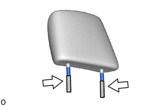

|
Application Area |

|
Apply Silicon |
Apply silicon lubricant to the application area.
- HINT:
-
The application area shown in the illustration is 20 + / -10 mm.
Install the front seat headrest assembly.