Home › Drivetrain › A343E AUTOMATIC TRANSMISSION / TRANSAXLE › AUTOMATIC TRANSMISSION SYSTEM
RM1880E _52 Drivetrain _013217 A343E AUTOMATIC TRANSMISSION / TRANSAXLE _0068504 AUTOMATIC TRANSMISSION SYSTEM J

A343E AUTOMATIC TRANSMISSION / TRANSAXLE  AUTOMATIC TRANSMISSION SYSTEM  Park / Neutral Position Switch Circuit  


DESCRIPTION

The Park/Neutral Position (PNP) switch detects the shift lever position and sends signals to the ECM.

WIRING DIAGRAM
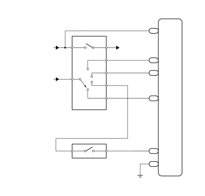
C229123
4.25,1.531 5.323,1.813 1.073,0.281 10 false to ST Relay 5.813,6.219 6.313,6.417 0.5,0.198 10 false ECM 5.594,0.979 6.094,1.177 0.5,0.198 10 false NSW 5.615,2.469 6.115,2.667 0.5,0.198 10 false 2 5.615,3.354 6.115,3.552 0.5,0.198 10 false L 5.615,2.021 6.115,2.219 0.5,0.198 10 false R 5.604,5.656 6.104,5.854 0.5,0.198 10 false E1 5.25,0.99 5.781,1.219 0.531,0.229 10 false G89 5.25,2.021 5.781,2.24 0.531,0.219 10 false G88 5.25,2.469 5.74,2.656 0.49,0.188 10 false G88 5.24,3.354 5.948,3.667 0.708,0.313 10 false G88 5.25,5.646 5.781,5.854 0.531,0.208 10 false C75 5.302,0.802 5.542,1 0.24,0.198 10 false 30 5.302,2.281 5.542,2.479 0.24,0.198 10 false 10 5.344,3.177 5.583,3.375 0.24,0.198 10 false 9 5.302,1.844 5.542,2.042 0.24,0.198 10 false 11 5.344,5.469 5.583,5.667 0.24,0.198 10 false 3 3.583,1.469 4.01,1.667 0.427,0.198 10 false L 3.5,1.906 3.927,2.104 0.427,0.198 10 false RL 3.5,2.354 3.927,2.552 0.427,0.198 10 false 2L 3.5,2.792 3.927,2.99 0.427,0.198 10 false DL 3.5,3.24 3.927,3.438 0.427,0.198 10 false LL 2.583,1.469 3.01,1.667 0.427,0.198 10 false B 2.583,2.573 3.01,2.771 0.427,0.198 10 false RB 2.396,1.677 2.635,1.875 0.24,0.198 10 false 4 3.792,1.677 4.031,1.875 0.24,0.198 10 false 5 3.792,2.125 4.031,2.323 0.24,0.198 10 false 1 3.792,2.563 4.031,2.76 0.24,0.198 10 false 3 3.792,3.01 4.031,3.208 0.24,0.198 10 false 7 3.792,3.458 4.031,3.656 0.24,0.198 10 false 8 2.396,2.802 2.635,3 0.24,0.198 10 false 2 2.219,4.031 4.594,4.271 2.375,0.24 10 false Park/Neutral Position Switch 2.219,3.865 2.615,4.063 0.396,0.198 10 false C26 2.385,5.76 3.938,5.958 1.552,0.198 10 false Shift Lock Control ECU 2.385,5.573 2.781,5.771 0.396,0.198 10 false G37 2.563,5.094 2.99,5.292 0.427,0.198 10 false NSSD 2.396,5.292 2.635,5.49 0.24,0.198 10 false 9 3.427,5.094 3.854,5.292 0.427,0.198 10 false AT3 3.792,5.292 4.031,5.49 0.24,0.198 10 false 3 0.979,1.573 1.917,1.771 0.938,0.198 10 false from ST Fuse 0.094,2.667 2.281,2.948 2.188,0.281 10 false from ECU-IG&GAUGE Fuse 5.615,5.198 6.115,5.396 0.5,0.198 10 false 3 5.24,5.198 5.729,5.385 0.49,0.188 10 false G88 5.302,5.021 5.542,5.219 0.24,0.198 10 false 19

PROCEDURE

1.CHECK PARK/NEUTRAL POSITION SWITCH ASSEMBLY (POWER SOURCE)
a.

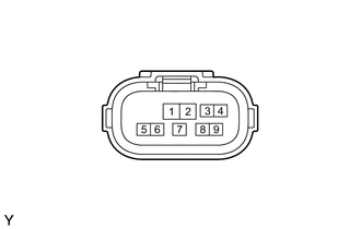
Disconnect the C26 park/neutral position switch connector.

b.
C197711
0.323,0.99 0.76,1.25 0.438,0.26 1.771,1.01 1.969,0.438 true 0.406,1.031 0.708,1.198 0.302,0.167 10 false C26 0.052,0.042 0.365,0.24 0.313,0.198 10 false *a 1.917,0.26 2.156,0.458 0.24,0.198 10 false RB
*a Front view of wire harness connector
(to Park/Neutral Position Switch)


Measure the voltage according to the value(s) in the table below.

Standard Voltage:
Tester Connection Switch Condition Specified Condition
C26-2 (RB) - Body ground Ignition switch ON 11 to 14 V
C26-2 (RB) - Body ground Ignition switch off Below 1 V


Result:
Proceed to
OK
NG


OK

2.CHECK HARNESS AND CONNECTOR (NSW TERMINAL VOLTAGE)

NG

REPAIR OR REPLACE HARNESS OR CONNECTOR

2.CHECK HARNESS AND CONNECTOR (NSW TERMINAL VOLTAGE)
a.

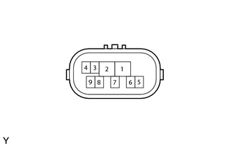
Disconnect the C26 park/neutral position switch connector.

b.
C197711
0.313,1 0.75,1.26 0.438,0.26 2.125,1.021 2.271,0.5 true 0.396,1.042 0.698,1.208 0.302,0.167 10 false C26 0.073,0.042 0.385,0.24 0.313,0.198 10 false *a 2.26,0.302 2.5,0.5 0.24,0.198 10 false B
*a Front view of wire harness connector
(to Park/Neutral Position Switch)


Measure the voltage according to the value(s) in the table below.

Standard Voltage:
Tester Connection Switch Condition Specified Condition
C26-4 (B) - Body ground Ignition switch ON 11 to 14 V
C26-4 (B) - Body ground Ignition switch off Below 1 V


Result:
Proceed to
OK
NG


OK

3.INSPECT PARK/NEUTRAL POSITION SWITCH ASSEMBLY

NG

7.CHECK HARNESS AND CONNECTOR (PARK/NEUTRAL POSITION SWITCH - ECM)
3.INSPECT PARK/NEUTRAL POSITION SWITCH ASSEMBLY
a.

Disconnect the C26 park/neutral position switch connector.


b.
C197712
1.271,0.958 0.927,0.427 true 1.823,0.948 2.208,0.427 true 1.406,0.948 1.271,0.427 true 1.604,0.948 1.75,0.427 true 1.354,1.729 1.479,1.281 true 1.792,1.719 1.708,1.281 true 2.167,1.719 2.083,1.271 true 0.052,0 0.365,0.198 0.313,0.198 10 false *a 0.833,0.25 1.063,0.448 0.229,0.198 10 false B 2.177,0.229 2.448,0.427 0.271,0.198 10 false RL 1.188,0.219 1.417,0.417 0.229,0.198 10 false 2L 1.688,0.219 1.927,0.417 0.24,0.198 10 false RB 1.25,1.75 1.521,1.948 0.271,0.198 10 false LL 1.729,1.75 1.969,1.948 0.24,0.198 10 false DL 2.156,1.75 2.427,1.948 0.271,0.198 10 false L
*a Component without harness connected
(Park/Neutral Position Switch)


Measure the resistance according to the value(s) in the table below.

Standard Resistance:
Tester Connection Condition Specified Condition
4 (B) - 5 (L) Shift lever in P Below 1 Ω
2 (RB) - 1 (RL) Shift lever in R Below 1 Ω
4 (B) - 5 (L) Shift lever in N Below 1 Ω
2 (RB) - 7 (DL) Shift lever in D or 3 Below 1 Ω
2 (RB) - 3 (2L) Shift lever in 2 Below 1 Ω
2 (RB) - 8 (LL) Shift lever in L Below 1 Ω
4 (B) - 5 (L) Shift lever not in P 10 kΩ or higher
2 (RB) - 1 (RL) Shift lever not in R 10 kΩ or higher
4 (B) - 5 (L) Shift lever not in N 10 kΩ or higher
2 (RB) - 7 (DL) Shift lever not in D or 3 10 kΩ or higher
2 (RB) - 3 (2L) Shift lever not in 2 10 kΩ or higher
2 (RB) - 8 (LL) Shift lever not in L 10 kΩ or higher


Result:
Proceed to
OK
NG


OK

4.INSPECT SHIFT LOCK CONTROL ECU

NG

4.INSPECT SHIFT LOCK CONTROL ECU
a.

Disconnect the G37 shift lock control ECU connector.
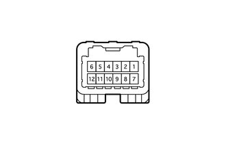

b.
C214966
2.49,0.625 1.792,0.958 true 1.802,1.24 2.5,1.573 true 0.063,0.083 0.302,0.281 0.24,0.198 10 false *a 2.563,0.542 3.01,0.74 0.448,0.198 10 false AT3 2.563,1.51 3.01,1.708 0.448,0.198 10 false NSSD
*a Component without harness connected
(Shift Lock Control ECU)


Measure the resistance according to the value(s) in the table below.

Standard Resistance:
Tester Connection Condition Specified Condition
3 (AT3) - 9 (NSSD) Shift lever in 3 Below 1 Ω
3 (AT3) - 9 (NSSD) Shift lever in D 10 kΩ or higher


Result:
Proceed to
OK
NG


OK

5.CHECK HARNESS AND CONNECTOR (PARK/NEUTRAL POSITION SWITCH - SHIFT LOCK CONTROL ECU)

NG

REPLACE SHIFT LOCK CONTROL ECU (SHIFT LOCK CONTROL UNIT ASSEMBLY)

5.CHECK HARNESS AND CONNECTOR (PARK/NEUTRAL POSITION SWITCH - SHIFT LOCK CONTROL ECU)
a.

Disconnect the G37 shift lock control ECU connector.
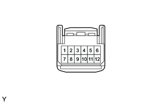

b.
C203405
0.406,0.854 0.844,1.115 0.438,0.26 1.615,1.302 1.25,1.667 true 0.49,0.896 0.865,1.125 0.375,0.229 10 false G37 0.063,0.052 0.375,0.25 0.313,0.198 10 false *a 0.833,1.656 1.25,1.854 0.417,0.198 10 false NSSD
*a Front view of wire harness connector
(to Shift Lock Control ECU)


Measure the voltage according to the value(s) in the table below.

Standard Voltage:
Tester Connection Condition Specified Condition
9 (NSSD) - Body ground
·

Ignition switch ON

·

Shift lever in D or 3


11 to 14 V
9 (NSSD) - Body ground
·

Ignition switch ON

·

Shift lever not in D or 3


Below 1 V


Result:
Proceed to
OK
NG


OK

6.CHECK HARNESS AND CONNECTOR (PARK/NEUTRAL POSITION SWITCH - ECM)

NG

REPAIR OR REPLACE HARNESS OR CONNECTOR

6.CHECK HARNESS AND CONNECTOR (PARK/NEUTRAL POSITION SWITCH - ECM)
a.
C238415
0.583,0.75 1.021,1.01 0.438,0.26 1.813,0.75 2.25,1.01 0.438,0.26 1.49,2.583 2.031,1.594 true 1.917,2.354 2.083,1.594 true 2.344,2.583 2.135,1.594 true 2.677,2.344 2.177,1.656 true 0.604,2.344 0.854,1.51 true 0.052,0.063 0.365,0.26 0.313,0.198 10 false *a 0.667,0.802 1.042,1.031 0.375,0.229 10 false C75 1.896,0.802 2.271,1.031 0.375,0.229 10 false G88 1.74,2.396 2.156,2.594 0.417,0.198 10 false 10 (2) 1.25,2.646 1.698,2.844 0.448,0.198 10 false 11 (R) 2.26,2.635 2.594,2.833 0.333,0.198 10 false 9 (L) 2.583,2.385 3.052,2.583 0.469,0.198 10 false 19 (3) 0.406,2.396 0.854,2.594 0.448,0.198 10 false 3 (E1)
*a Rear view of wire harness connector
(to ECM)


Measure the voltage according to the value(s) in the table below.

Standard Voltage:
Tester Connection Condition Specified Condition
G88-11 (R) - C75-3 (E1)
·

Ignition switch ON

·

Shift lever in R


11 to 14 V*
G88-19 (3) - C75-3 (E1)
·

Ignition switch ON

·

Shift lever in 3


11 to 14 V
G88-10 (2) - C75-3 (E1)
·

Ignition switch ON

·

Shift lever in 2


11 to 14 V
G88-9 (L) - C75-3 (E1)
·

Ignition switch ON

·

Shift lever in L


11 to 14 V
G88-11 (R) - C75-3 (E1)
·

Ignition switch ON

·

Shift lever not in R


Below 1 V
G88-19 (3) - C75-3 (E1)
·

Ignition switch ON

·

Shift lever not in 3


Below 1 V
G88-10 (2) - C75-3 (E1)
·

Ignition switch ON

·

Shift lever not in 2


Below 1 V
G88-9 (L) - C75-3 (E1)
·

Ignition switch ON

·

Shift lever not in L


Below 1 V


HINT:

*: The voltage will drop slightly due to the illumination of the back-up light.


Result:
Proceed to
OK
NG


OK

NG

REPAIR OR REPLACE HARNESS OR CONNECTOR

7.CHECK HARNESS AND CONNECTOR (PARK/NEUTRAL POSITION SWITCH - ECM)
a.

Disconnect the C26 park/neutral position switch connector.


b.

Disconnect the G89 ECM connector.


c.

Measure the resistance according to the value(s) in the table below.

Standard Resistance:
Tester Connection Condition Specified Condition
C26-4 (B) - G89-30 (NSW) Always Below 1 Ω
C26-4 (B) - Body ground Always 10 kΩ or higher


Result:
Proceed to
OK
NG


OK

NG

REPAIR OR REPLACE HARNESS OR CONNECTOR