FRONT SUSPENSION FRONT LOWER SUSPENSION ARM REMOVAL
CAUTION / NOTICE / HINT
- HINT:
- ·
Use the same procedure for the RH and LH sides.
·The procedure listed below is for the LH side.
PROCEDURE

 1.REMOVE FRONT WHEEL
2.REMOVE FRONT SPEED SENSOR LH
3.DISCONNECT FRONT SHOCK ABSORBER WITH COIL SPRING
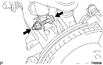
Remove the nut and bolt.
- HINT:
-
While fixing the nut in place, loosen and remove the bolt.
Disconnect the shock absorber with coil spring from the lower arm.
4.DISCONNECT FRONT STABILIZER LINK ASSEMBLY LH
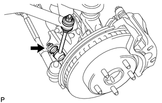
Remove the nut and disconnect the stabilizer link from the lower arm.
- HINT:
-
If the ball joint turns together with the nut, use a 6 mm hexagon wrench to hold the stud in place.
5.REMOVE FRONT SPRING BUMPER
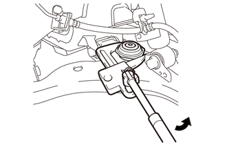
| *a | Turn |
Using SST, remove the front spring bumper.
- SST
- 09922-10010
- NOTICE:
-
Rotate SST in the direction shown in the illustration.
6.REMOVE FRONT LOWER SUSPENSION ARM SUB-ASSEMBLY LH
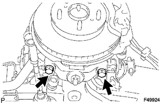
Remove the 2 bolts, and disconnect the ball joint attachment from the steering knuckle.
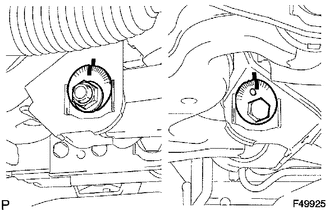
| *1 | Matchmark |
Place matchmarks on the No. 1 camber adjusting cam and vehicle frame, and No. 2 camber adjusting cam and vehicle frame.
Remove the 2 nuts, No. 1 and No. 2 camber adjusting cams, 2 camber adjusting cams and lower arm.
7.REMOVE FRONT LOWER BALL JOINT ATTACHMENT LH
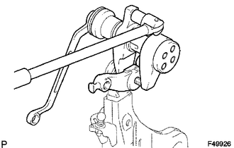
Remove the cotter pin and nut.
Using SST, remove the ball joint attachment.
- SST
- 09628-00011
8.REMOVE FRONT NO. 1 LOWER ARM BUSH
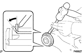
Using a hammer and chisel, strike and bend the entire flange of the bush as shown in the illustration.
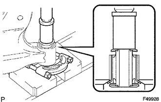
Using SST, and a press, press out the bush.
- SST
- 09632-36010
09950-00020
09950-60010 (09951-00520)
9.REMOVE FRONT NO. 2 LOWER ARM BUSH
Using a hammer and chisel, strike and bend the entire flange of the bush as shown in the illustration.
Using SST and a press, press out the bush.
- SST
- 09632-36010
09950-00020
09950-60010 (09951-00520)
10.REMOVE LOWER BALL JOINT ASSEMBLY
| *a | Protective tape |
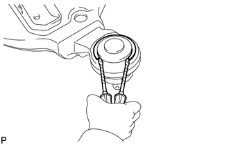
Using 2 screwdrivers and a hammer, remove the snap ring.
- HINT:
-
Tape the screwdriver tip before use.
Remove the dust cover set ring and dust cover from the lower arm.
| *a | Hold |
| *b | Turn |
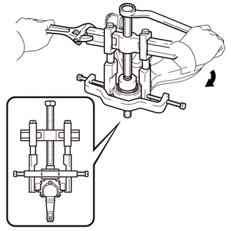
Using SST, remove the ball joint.
- SST
- 09950-40011 (09951-04010, 09952-04010, 09953-04020, 09954-04010, 09955-04031, 09957-04010, 09958-04011)
09710-22021 (09710-01081)