SEAT REAR NO. 1 SEAT ASSEMBLY(for 60/40 Split Tumble Seat Type LH Side) REASSEMBLY
CAUTION / NOTICE / HINT
- CAUTION:
-
Wear protective gloves. Sharp areas on the parts may injure your hands.
PROCEDURE

 1.INSTALL NO. 1 FOLD SEAT STOPPER BAND ASSEMBLY
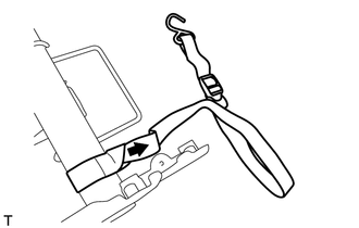
Tie the No. 1 fold seat stopper band assembly to the rear No. 1 seat cushion frame as shown in the illustration to install the No. 1 fold seat stopper band assembly.
2.INSTALL NO. 1 SEAT CUSHION PAD LH
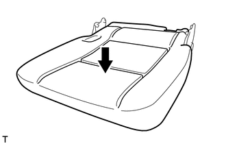
Install the rear No. 1 seat cushion pad LH to the rear No. 1 seat cushion frame.
3.INSTALL REAR NO. 1 SEAT CUSHION COVER LH
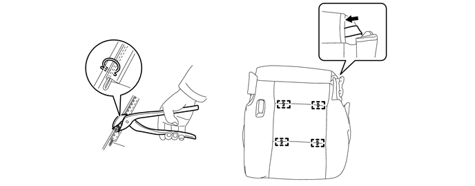
| *1 | No. 1 Fold Seat Stopper Band Assembly | *2 | Hog Ring Pliers |
Using hog ring pliers, install the rear No. 1 seat cushion cover LH to the No. 1 seat cushion pad LH with new hog rings.
- NOTICE:
- ·
Be careful not to damage the cover.
·When installing the hog rings, avoid wrinkling the cover.
Insert the No. 1 fold seat stopper band assembly into the rear No. 1 seat cushion cover LH.
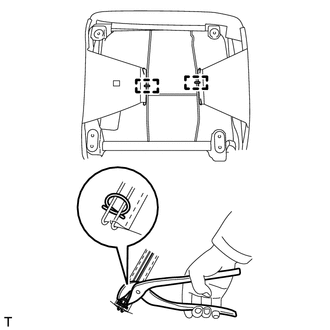
| *1 | Hog Ring Pliers |
Using hog ring pliers, install new hog rings.
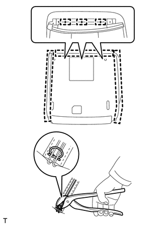
| *1 | Rear No. 1 Seat Cushion Cover LH Front Part |
| *2 | Fastening Tape |
| *3 | Fastener |
| *4 | Hog Ring Pliers |
Attach the 2 fasteners to close the rear No. 1 seat cushion cover.
Using hog ring pliers, install new hog rings.
Attach the fastening tape to close the front part of the rear No. 1 seat cushion cover LH.
4.INSTALL REAR SEAT TRACK ASSEMBLY LH
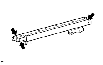

|
MP Grease |
Apply MP grease to the locations of the outer seat track assembly LH shown in the illustration.
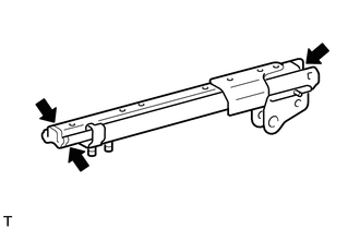
|
|
MP Grease |
Apply MP grease to the locations of the inner seat track assembly LH shown in the illustration.
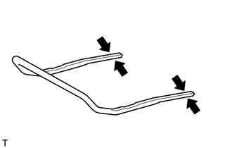
|
|
MP Grease |
Apply MP grease to the locations of the seat track adjusting handle shown in the illustration.
If reusing the outer seat track assembly LH and inner seat track assembly LH:
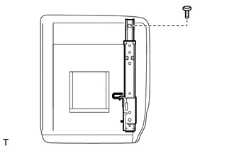
Using a T40 "TORX" socket wrench, temporarily install the front side of the outer seat track assembly LH with the "TORX" bolt.
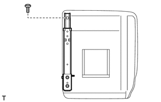
Using a T40 "TORX" socket wrench, temporarily install the front side of the inner seat track assembly LH with the "TORX" bolt.
Push the seat track adjusting handle into the outer seat track assembly LH and inner seat track assembly LH and engage the 2 seat track adjusting handle locks to install the seat track adjusting handle.
- NOTICE:
-
Make sure the handle is straight when installing it, and check that it is centered.
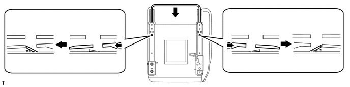
| *1 | Outer Seat Track Assembly LH | *2 | Seat Track Adjusting Handle Lock |
| *3 | Seat Track Adjusting Handle | *4 | Inner Seat Track Assembly LH |
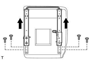
Operate the seat track adjusting handle and move the outer seat track assembly LH and inner seat track assembly LH to the foremost position.
Using a T40 "TORX" socket wrench, install the rear side of the outer seat track assembly LH and inner seat track assembly LH with the 4 "TORX" bolts.
- Torque:
- 40 N*m (408 kgf*cm, 30 ft.*lbf)
Operate the seat track adjusting handle and move the outer seat track assembly LH and inner seat track assembly LH to the position shown in the illustration.
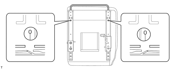
| *1 | Seat Track Adjusting Handle Lock | *2 | Outer Seat Track Assembly LH |
| *3 | Inner Seat Track Assembly LH | *4 | Seat Track Adjusting Handle |
Insert a screwdriver into the outer seat track assembly LH and disengage the lock of the seat track adjusting handle. While maintaining that state, pull out the seat track adjusting handle to the position shown in the illustration, and then remove the screwdriver.
- NOTICE:
-
Do not use excessive force to pull out the seat track adjusting handle.
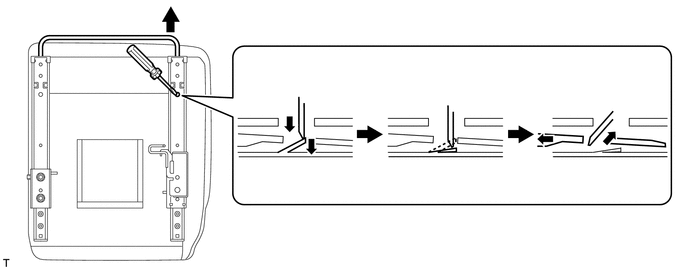
| *1 | Screwdriver | *2 | Outer Seat Track Assembly LH |
| *3 | Seat Track Adjusting Handle Lock | *4 | Seat Track Adjusting Handle |
Insert a screwdriver into the inner seat track assembly LH and disengage the lock of the seat track adjusting handle. While maintaining that state, pull out the seat track adjusting handle to the position shown in the illustration, and then remove the screwdriver.
- NOTICE:
-
Do not use excessive force to pull out the seat track adjusting handle.
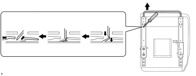
| *1 | Screwdriver | *2 | Inner Seat Track Assembly LH |
| *3 | Seat Track Adjusting Handle Lock | *4 | Seat Track Adjusting Handle |
Pull the seat track adjusting handle to the position shown in the illustration.
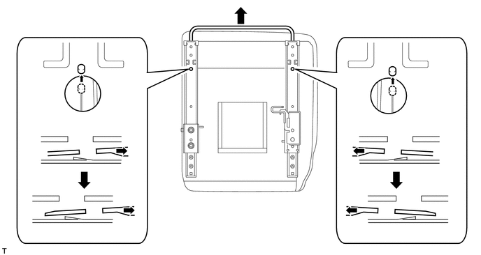
| *1 | Seat Track Adjusting Handle Lock | *2 | Outer Seat Track Assembly LH |
| *3 | Inner Seat Track Assembly LH | *4 | Seat Track Adjusting Handle |
- NOTICE:
- ·
At this time, do not remove the seat track adjusting handle.
·At this time, do not engage the lock of the seat track adjusting handle.
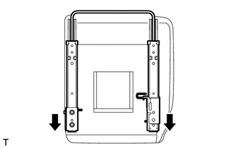
Operate the seat track adjusting handle and move the outer seat track assembly LH and inner seat track assembly LH to the rearmost position.
- NOTICE:
-
At this time, do not engage the lock of the seat track adjusting handle.
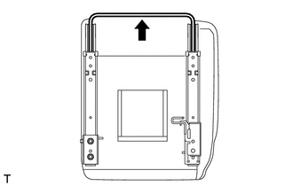
Pull and remove the seat track adjusting handle from the outer seat track assembly LH and inner seat track assembly LH.
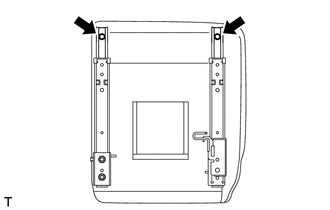
Using a T40 "TORX" socket wrench, tighten the 2 "TORX" bolts on the front side of the outer seat track assembly LH and inner seat track assembly LH.
- Torque:
- 40 N*m (408 kgf*cm, 30 ft.*lbf)
Push the seat track adjusting handle into the outer seat track assembly LH and inner seat track assembly LH and engage the 2 seat track adjusting handle locks to install the seat track adjusting handle.
- NOTICE:
-
Make sure the handle is straight when installing it, and check that it is centered.
| *1 | Outer Seat Track Assembly LH | *2 | Seat Track Adjusting Handle Lock |
| *3 | Seat Track Adjusting Handle | *4 | Inner Seat Track Assembly LH |
If replacing the outer seat track assembly LH with a new one but reusing the inner seat track assembly LH:
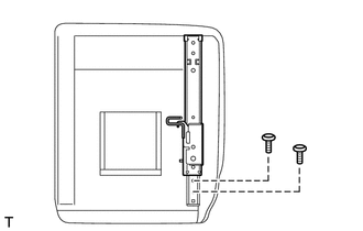
Using a T40 "TORX" socket wrench, temporarily install the rear side of a new outer seat track assembly LH with the 2 "TORX" bolts.
Using a T40 "TORX" socket wrench, temporarily install the front side of the inner seat track assembly LH with the "TORX" bolt.
Push the seat track adjusting handle into the outer seat track assembly LH and engage the seat track adjusting handle lock to install the seat track adjusting handle.
- NOTICE:
-
Make sure the handle is straight when installing it, and check that it is centered.
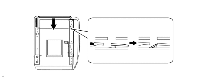
| *1 | Outer Seat Track Assembly LH | *2 | Seat Track Adjusting Handle Lock |
| *3 | Seat Track Adjusting Handle | - | - |
Operate the seat track adjusting handle and, while moving the outer seat track assembly LH toward the rearmost position, insert the handle into the inner seat track assembly LH and engage the lock of the seat track adjusting handle to install the handle.
- NOTICE:
-
Make sure the handle is straight when installing it, and check that it is centered.
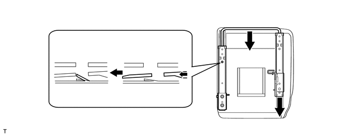
| *1 | Inner Seat Track Assembly LH | *2 | Seat Track Adjusting Handle Lock |
| *3 | Seat Track Adjusting Handle | - | - |
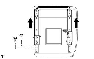
Operate the seat track adjusting handle and move the outer seat track assembly LH and inner seat track assembly LH to the foremost position.
Using a T40 "TORX" socket wrench, install the rear side of the inner seat track assembly LH with the 2 "TORX" bolts.
- Torque:
- 40 N*m (408 kgf*cm, 30 ft.*lbf)
Operate the seat track adjusting handle and move the outer seat track assembly LH and inner seat track assembly LH to the position shown in the illustration.
| *1 | Seat Track Adjusting Handle Lock | *2 | Outer Seat Track Assembly LH |
| *3 | Inner Seat Track Assembly LH | *4 | Seat Track Adjusting Handle |
Insert a screwdriver into the outer seat track assembly LH and disengage the lock of the seat track adjusting handle. While maintaining that state, pull out the seat track adjusting handle to the position shown in the illustration, and then remove the screwdriver.
- NOTICE:
-
Do not use excessive force to pull out the seat track adjusting handle.
| *1 | Screwdriver | *2 | Outer Seat Track Assembly LH |
| *3 | Seat Track Adjusting Handle Lock | *4 | Seat Track Adjusting Handle |
Insert a screwdriver into the inner seat track assembly LH and disengage the lock of the seat track adjusting handle. While maintaining that state, pull out the seat track adjusting handle to the position shown in the illustration.
- NOTICE:
-
Do not use excessive force to pull out the seat track adjusting handle.
| *1 | Screwdriver | *2 | Inner Seat Track Assembly LH |
| *3 | Seat Track Adjusting Handle Lock | *4 | Seat Track Adjusting Handle |
Pull the seat track adjusting handle to the position shown in the illustration.
| *1 | Seat Track Adjusting Handle Lock | *2 | Outer Seat Track Assembly LH |
| *3 | Inner Seat Track Assembly LH | *4 | Seat Track Adjusting Handle |
- NOTICE:
- ·
At this time, do not remove the seat track adjusting handle.
·At this time, do not engage the lock of the seat track adjusting handle.
Operate the seat track adjusting handle and move the outer seat track assembly LH and inner seat track assembly LH to the rearmost position.
- NOTICE:
-
At this time, do not engage the lock of the seat track adjusting handle.
Pull and remove the seat track adjusting handle from the outer seat track assembly LH and inner seat track assembly LH.
Using a T40 "TORX" socket wrench, install the front side of the outer seat track assembly LH with the "TORX" bolt.
- Torque:
- 40 N*m (408 kgf*cm, 30 ft.*lbf)
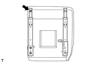
Using a T40 "TORX" socket wrench, tighten the "TORX" bolt on the front side of the inner seat track assembly LH.
- Torque:
- 40 N*m (408 kgf*cm, 30 ft.*lbf)
Push the seat track adjusting handle into the outer seat track assembly LH and inner seat track assembly LH and engage the 2 seat track adjusting handle locks to install seat track adjusting handle.
- NOTICE:
-
Make sure the handle is straight when installing it, and check that it is centered.
| *1 | Outer Seat Track Assembly LH | *2 | Seat Track Adjusting Handle Lock |
| *3 | Seat Track Adjusting Handle | *4 | Inner Seat Track Assembly LH |
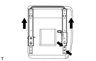
Operate the seat track adjusting handle and move the outer seat track assembly LH and inner seat track assembly LH to the foremost position.
Using a T40 "TORX" socket wrench, tighten the 2 "TORX" bolts on the rear side of the outer seat track assembly LH.
- Torque:
- 40 N*m (408 kgf*cm, 30 ft.*lbf)
If replacing the inner seat track assembly LH with a new one but reusing the outer seat track assembly LH:
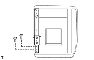
Using a T40 "TORX" socket wrench, temporarily install the rear side of a new inner seat track assembly LH with the 2 "TORX" bolts.
Using a T40 "TORX" socket wrench, temporarily install the front side of the outer seat track assembly LH with the "TORX" bolt.
Push the seat track adjusting handle into the inner seat track assembly LH and engage the seat track adjusting handle lock to install the seat track adjusting handle.
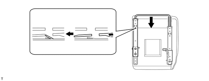
| *1 | Inner Seat Track Assembly LH | *2 | Seat Track Adjusting Handle Lock |
| *3 | Seat Track Adjusting Handle | - | - |
Operate the seat track adjusting handle and, while moving the inner seat track assembly LH toward the rearmost position, insert the handle into the outer seat track assembly LH and engage the lock of the seat track adjusting handle to install the handle.
- NOTICE:
-
Make sure the handle is straight when installing it, and check that it is centered.
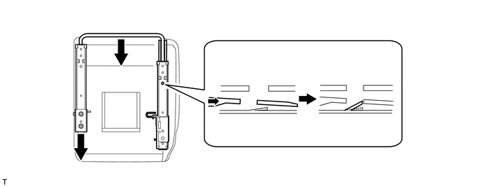
| *1 | Outer Seat Track Assembly LH | *2 | Seat Track Adjusting Handle Lock |
| *3 | Seat Track Adjusting Handle | - | - |
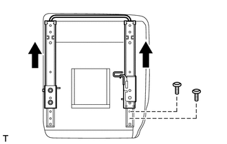
Operate the seat track adjusting handle and move the outer seat track assembly LH and inner seat track assembly LH to the foremost position.
Using a T40 "TORX" socket wrench, install the rear side of the outer seat track assembly LH with the 2 "TORX" bolts.
- Torque:
- 40 N*m (408 kgf*cm, 30 ft.*lbf)
Operate the seat track adjusting handle and move the outer seat track assembly LH and inner seat track assembly LH to the position shown in the illustration.
| *1 | Seat Track Adjusting Handle Lock | *2 | Outer Seat Track Assembly LH |
| *3 | Inner Seat Track Assembly LH | *4 | Seat Track Adjusting Handle |
Insert a screwdriver into the outer seat track assembly LH and disengage the lock of the seat track adjusting handle. While maintaining that state, pull out the seat track adjusting handle to the position shown in the illustration, and then remove the screwdriver.
- NOTICE:
-
Do not use excessive force to pull out the seat track adjusting handle.
| *1 | Screwdriver | *2 | Outer Seat Track Assembly LH |
| *3 | Seat Track Adjusting Handle Lock | *4 | Seat Track Adjusting Handle |
Insert a screwdriver into the inner seat track assembly LH and disengage the lock of the seat track adjusting handle. While maintaining that state, pull out the seat track adjusting handle to the position shown in the illustration, and then remove the screwdriver.
- NOTICE:
-
Do not use excessive force to pull out the seat track adjusting handle.
| *1 | Screwdriver | *2 | Inner Seat Track Assembly LH |
| *3 | Seat Track Adjusting Handle Lock | *4 | Seat Track Adjusting Handle |
Pull the seat track adjusting handle to the position shown in the illustration.
| *1 | Seat Track Adjusting Handle Lock | *2 | Outer Seat Track Assembly LH |
| *3 | Inner Seat Track Assembly LH | *4 | Seat Track Adjusting Handle |
- NOTICE:
- ·
At this time, do not remove the seat track adjusting handle.
·At this time, do not engage the lock of the seat track adjusting handle.
Operate the seat track adjusting handle and move the outer seat track assembly LH and inner seat track assembly LH to the rearmost position.
- NOTICE:
-
At this time, do not engage the lock of the seat track adjusting handle.
Pull and remove the seat track adjusting handle from the outer seat track assembly LH and inner seat track assembly LH.
Using a T40 "TORX" socket wrench, install the front side of the inner seat track assembly LH with the "TORX" bolt.
- Torque:
- 40 N*m (408 kgf*cm, 30 ft.*lbf)
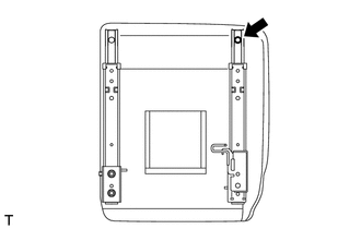
Using a T40 "TORX" socket wrench, tighten the "TORX" bolt on the front side of the outer seat track assembly LH.
- Torque:
- 40 N*m (408 kgf*cm, 30 ft.*lbf)
Push the seat track adjusting handle into the outer seat track assembly LH and inner seat track assembly LH and engage the 2 seat track adjusting handle locks to install the seat track adjusting handle.
- NOTICE:
-
Make sure the handle is straight when installing it, and check that it is centered.
| *1 | Outer Seat Track Assembly LH | *2 | Seat Track Adjusting Handle Lock |
| *3 | Seat Track Adjusting Handle | *4 | Inner Seat Track Assembly LH |
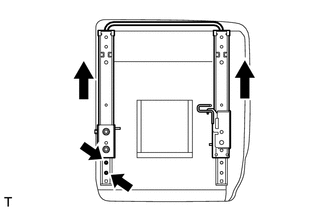
Operate the seat track adjusting handle and move the outer seat track assembly LH and inner seat track assembly LH to the foremost position.
Using a T40 "TORX" socket wrench, tighten the 2 "TORX" bolts on the rear side of the inner seat track assembly LH.
- Torque:
- 40 N*m (408 kgf*cm, 30 ft.*lbf)
If replacing both the outer seat track assembly LH and inner seat track assembly LH with new ones:
Using a T40 "TORX" socket wrench, temporarily install the rear side of a new outer seat track assembly LH with the 2 "TORX" bolts.
Using a T40 "TORX" socket wrench, temporarily install the rear side of a new inner seat track assembly LH with the 2 "TORX" bolts.
Push the seat track adjusting handle into the outer seat track assembly LH and inner seat track assembly LH and engage the 2 seat track adjusting handle locks to install the seat track adjusting handle.
- NOTICE:
-
Make sure the handle is straight when installing it, and check that it is centered.
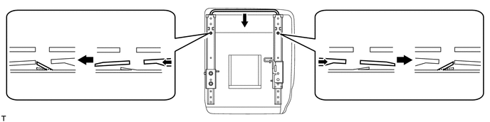
| *1 | Outer Seat Track Assembly LH | *2 | Seat Track Adjusting Handle Lock |
| *3 | Seat Track Adjusting Handle | *4 | Inner Seat Track Assembly LH |
Operate the seat track adjusting handle and move the outer seat track assembly LH and inner seat track assembly LH to the position shown in the illustration.
| *1 | Seat Track Adjusting Handle Lock | *2 | Outer Seat Track Assembly LH |
| *3 | Inner Seat Track Assembly LH | *4 | Seat Track Adjusting Handle |
Insert a screwdriver into the outer seat track assembly LH and disengage the lock of the seat track adjusting handle. While maintaining that state, pull out the seat track adjusting handle to the position shown in the illustration, and then remove the screwdriver.
- NOTICE:
-
Do not use excessive force to pull out the seat track adjusting handle.
| *1 | Screwdriver | *2 | Outer Seat Track Assembly LH |
| *3 | Seat Track Adjusting Handle Lock | *4 | Seat Track Adjusting Handle |
Insert a screwdriver into the inner seat track assembly LH and disengage the lock of the seat track adjusting handle. While maintaining that state, pull out the seat track adjusting handle to the position shown in the illustration, and then remove the screwdriver.
- NOTICE:
-
Do not use excessive force to pull out the seat track adjusting handle.
| *1 | Screwdriver | *2 | Inner Seat Track Assembly LH |
| *3 | Seat Track Adjusting Handle Lock | *4 | Seat Track Adjusting Handle |
Pull the seat track adjusting handle to the position shown in the illustration.
| *1 | Seat Track Adjusting Handle Lock | *2 | Outer Seat Track Assembly LH |
| *3 | Inner Seat Track Assembly LH | *4 | Seat Track Adjusting Handle |
- NOTICE:
- ·
At this time, do not remove the seat track adjusting handle.
·At this time, do not engage the lock of the seat track adjusting handle.
Operate the seat track adjusting handle and move the outer seat track assembly LH and inner seat track assembly LH to the rearmost position.
- NOTICE:
-
At this time, do not engage the lock of the seat track adjusting handle.
Pull and remove the seat track adjusting handle from the outer seat track assembly LH and inner seat track assembly LH.
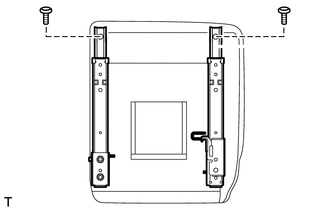
Using a T40 "TORX" socket wrench, install the front side of the inner seat track assembly LH and outer seat track assembly LH with the 2 "TORX" bolts.
- Torque:
- 40 N*m (408 kgf*cm, 30 ft.*lbf)
Push the seat track adjusting handle into the outer seat track assembly LH and inner seat track assembly LH and engage the 2 seat track adjusting handle locks to install the seat track adjusting handle.
| *1 | Outer Seat Track Assembly LH | *2 | Seat Track Adjusting Handle Lock |
| *3 | Seat Track Adjusting Handle | *4 | Inner Seat Track Assembly LH |
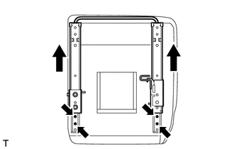
Operate the seat track adjusting handle and move the outer seat track assembly LH and inner seat track assembly LH to the foremost position.
Using a T40 "TORX" socket wrench, tighten the 4 "TORX" bolts on the rear side of the outer seat track assembly LH and inner seat track assembly LH.
- Torque:
- 40 N*m (408 kgf*cm, 30 ft.*lbf)
5.INSTALL SEAT TRACK ADJUSTING HANDLE
- HINT:
-
Perform this procedure when removing and reinstalling or replacing only the seat track adjusting handle.
|
|
MP Grease |
Apply MP grease to the locations of the seat track adjusting handle shown in the illustration.
Push the seat track adjusting handle into the outer seat track assembly LH and inner seat track assembly LH and engage the 2 seat track adjusting handle locks to install the seat track adjusting handle.
| *1 | Outer Seat Track Assembly LH | *2 | Seat Track Adjusting Handle Lock |
| *3 | Seat Track Adjusting Handle | *4 | Inner Seat Track Assembly LH |
6.INSTALL REAR SEAT LOCK ASSEMBLY RH
|
|
MP Grease |
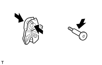
Apply MP grease to the locations of the rear seat lock assembly RH and "TORX" bolt shown in the illustration.
Using a T40 "TORX" socket wrench, install the rear seat lock assembly RH to the inner seat track assembly LH with the "TORX" bolt.
- Torque:
- 40 N*m (408 kgf*cm, 30 ft.*lbf)
7.INSTALL REAR SEAT NO. 1 CUSHION SUPPORT SPRING
Using needle nose pliers, install the rear seat No. 1 cushion support spring.
8.INSTALL REAR SEAT LOCK ASSEMBLY LH
Install the washer to the outer seat track assembly LH.
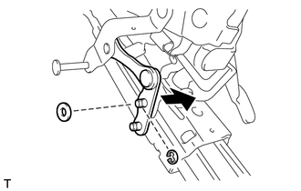
| *1 | Rear Seat Lock Link |
Connect the rear seat lock link to the outer seat track assembly LH with the washer and a new E-ring.
Install the rear seat lock assembly LH with the 2 nuts.
- Torque:
- 20 N*m (204 kgf*cm, 15 ft.*lbf)
9.INSTALL REAR SEAT CUSHION SUPPORT SPRING
Using needle nose pliers, install the rear seat cushion support spring.
10.INSTALL REAR SEAT LOCK CONTROL CABLE LH
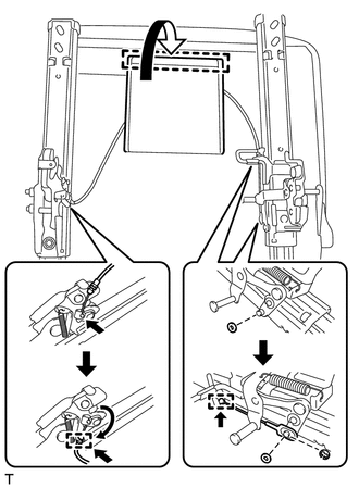
| *1 | Fastening Tape |
| *2 | Rear No. 1 Seat Cushion Cover LH Lower Part |
| *3 | Cable End |
| *4 | Cable Clamp |
Insert the cable end and twist it in the direction indicated by the arrow to connect the rear seat lock control cable LH to the rear seat lock assembly RH.
Attach the cable clamp.
Install the washer and connect the rear seat lock control cable LH to the rear seat lock assembly LH.
Install the washer and a new E-ring to the rear seat lock assembly LH.
Attach the cable clamp to install the rear seat lock control cable LH.
Attach the fastening tape to close the lower part of the rear No. 1 seat cushion cover LH.
11.INSTALL REAR SEAT HINGE ASSEMBLY LH
Install the rear seat hinge assembly LH with the 2 nuts.
- Torque:
- 42 N*m (428 kgf*cm, 31 ft.*lbf)
12.INSTALL REAR SEAT HINGE ASSEMBLY RH
- HINT:
-
Use the same procedure described for the LH side.
13.INSTALL NO. 1 SEAT LEG LINK
Install the 2 washers to the rear seat hinge assembly RH and rear seat lock assembly RH.
Install the No. 1 seat leg link with the 2 washers and 2 new E-rings to the rear seat hinge assembly RH and rear seat lock assembly RH.
14.INSTALL LOWER SEAT TRACK RAIL PROTECTOR RH
Attach the 2 claws to install the lower seat track rail protector RH to the inner seat track assembly LH.
Install the screw.
15.INSTALL LOWER SEAT TRACK RAIL PROTECTOR LH
Attach the 4 claws to install the lower seat track rail protector LH to the outer seat track assembly LH.
16.INSTALL REAR SEAT INNER LOCK COVER LH
Attach the guide and claw to install the rear seat inner lock cover LH to the rear seat lock assembly RH.
17.INSTALL REAR SEAT OUTER LOCK COVER LH
Attach the 2 claws to install the rear seat outer lock cover LH.
Install the screw.
18.INSTALL REAR PROTECTOR PIPE
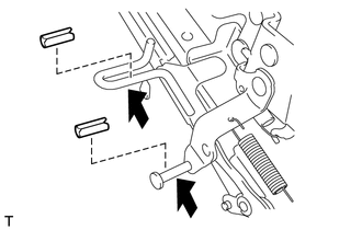
|
|
MP Grease |
Apply MP grease to the locations shown in the illustration.
Install the 2 rear protector pipes.
19.INSTALL RECLINING RELEASE HANDLE SUB-ASSEMBLY
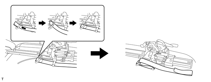
Install the reclining release handle sub-assembly as shown in the illustration.
20.INSTALL REAR SEAT LOCK COVER LH
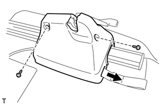
| *1 | Reclining Release Handle Sub-assembly |
Pass the reclining release handle sub-assembly through the hole of the rear seat lock cover LH.
Install the rear seat lock cover LH with the 2 screws.
21.INSTALL REAR SEATBACK LOCK RELEASE BUTTON
Install the 2 rear seatback lock release buttons to the reclining release handle sub-assembly.
22.INSTALL NO. 1 SEATBACK PAD LH
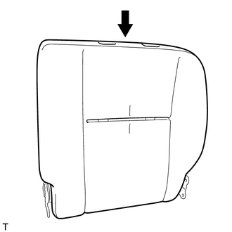
Install the No. 1 seatback pad LH to the rear No. 1 seatback frame.
23.INSTALL REAR NO. 1 SEATBACK COVER LH
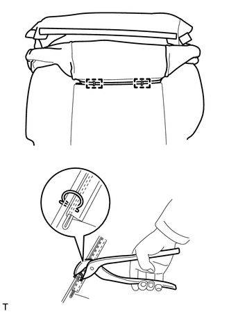
| *1 | Hog Ring Pliers |
Using hog ring pliers, install the rear No. 1 seatback cover LH to the No. 1 seatback pad LH with new hog rings.
- NOTICE:
- ·
Be careful not to damage the cover.
·When installing the hog rings, avoid wrinkling the cover.
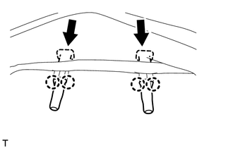
Attach the 4 claws to install the 2 rear seat headrest supports.
Attach the 2 hooks.
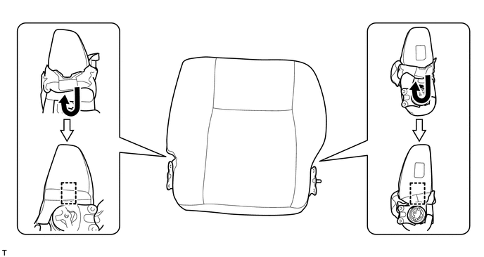
Attach the 3 hooks.
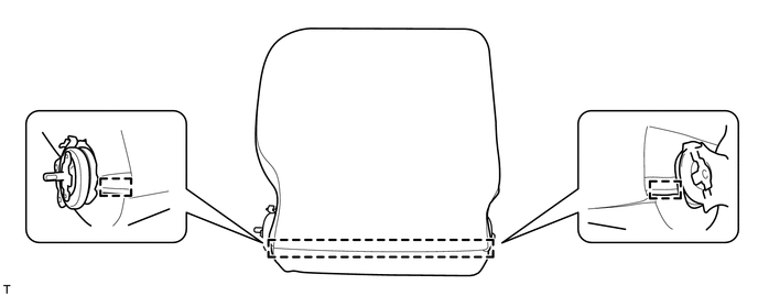
24.INSTALL REAR NO. 1 SEATBACK ASSEMBLY
Install the rear No. 1 seatback assembly with the 4 bolts.
- Torque:
- 50 N*m (510 kgf*cm, 37 ft.*lbf)
25.INSTALL REAR NO. 1 SEAT INNER BELT ASSEMBLY LH
26.INSTALL REAR NO. 1 SEAT RECLINING COVER RH
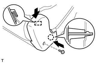
Attach the guide and claw to install the rear No. 1 seat reclining cover RH.
Install the screw.
27.INSTALL REAR NO. 1 SEAT RECLINING COVER LH
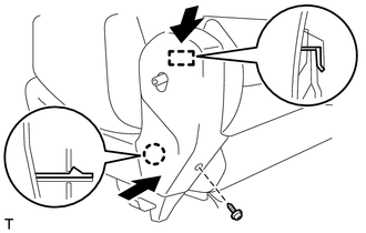
Attach the guide and claw to install the rear No. 1 seat reclining cover LH.
Install the screw.
28.INSTALL NO. 1 RECLINING ADJUSTER RELEASE HANDLE LH
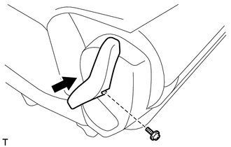
Install the No. 1 reclining adjuster release handle LH with the screw.
29.INSTALL REAR SEAT HEADREST ASSEMBLY
Install the rear seat headrest assembly.