HEATING / AIR CONDITIONING AIR CONDITIONING SYSTEM(for Automatic Air Conditioning System) 14 Engine Coolant Temperature Communication Circuit
DESCRIPTION
The engine coolant temperature sensor connected to the ECM detects the engine coolant temperature, which is used for warm up control when the engine is cold. The engine coolant temperature sensor sends a signal to the air conditioning amplifier assembly via the ECM.
| DTC No. | Detection Item | DTC Detection Condition | Trouble Area | Memory | Note |
|---|---|---|---|---|---|
| 14 | Engine Coolant Temperature Communication Circuit | An open or short in engine coolant temperature communication circuit | ·
ECD system ·
Air conditioning amplifier assembly ·
Harness or connector |
Memorized
(8.5 min. or more) |
- |
- HINT:
-
Memory: The air conditioning amplifier stores the DTC of the respective malfunction that has been detected for the period of time indicated in parentheses.
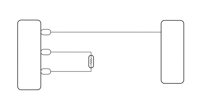
WIRING DIAGRAM
PROCEDURE
Clear the DTCs.
Click hereEngine / Hybrid System>2TR-FE ENGINE CONTROL>SFI SYSTEM>DTC CHECK / CLEAR
Check the DTC.
Click hereEngine / Hybrid System>2TR-FE ENGINE CONTROL>SFI SYSTEM>DTC CHECK / CLEAR
- Result:
Result Proceed to DTC (P0115, P0117 or P0118) is not output. A DTC (P0115, P0117 or P0118) is output. B
A
B
Click hereEngine / Hybrid System>2TR-FE ENGINE CONTROL>SFI SYSTEM>HOW TO PROCEED WITH TROUBLESHOOTING
Disconnect the G94 air conditioning amplifier assembly connector.
Disconnect the G88 ECM connector.
Measure the resistance according to the value(s) in the table below.
- Standard Resistance:
Tester Connection Condition Specified Condition G94-8 (TW) - G88-14 (THWO) Always Below 1 Ω G94-8 (TW) - Body ground Always 10 kΩ or higher
- Result:
Result Proceed to OK (When troubleshooting according to problem symptoms table.) A OK (When troubleshooting according to DTC.) B NG C
A
B
C