MIRROR (EXT) OUTER REAR VIEW MIRROR INSPECTION
PROCEDURE

 1.INSPECT OUTER REAR VIEW MIRROR ASSEMBLY LH
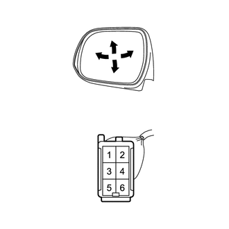
| *a | Component without harness connected
(Outer Rear View Mirror Assembly LH) |
Disconnect the mirror connector.
Apply battery voltage and check operation of the mirror.
- OK:
Measurement Condition Specified Condition Battery positive (+) →Terminal 5 (MV)
Battery negative (-) → Terminal 3 (M+)Turns upward Battery positive (+) → Terminal 3 (M+)
Battery negative (-) → Terminal 5 (MV)Turns downward Battery positive (+) → Terminal 1 (MH)
Battery negative (-) → Terminal 3 (M+)Turns left Battery positive (+) → Terminal 3 (M+)
Battery negative (-) → Terminal 1 (MH)Turns right
If the result is not as specified, replace the outer rear view mirror assembly LH.
w/ side turn signal light:
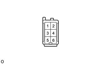
Check the side turn signal light.
Apply battery voltage to the terminals of the connector, and check the illumination condition.
- OK:
Tester Connection Specified Condition Battery positive (+) → Terminal 4 (B)
Battery negative (-) → Terminal 2 (E)Side turn light illuminates
If the result is not as specified, replace the side turn signal light assembly LH (See page Vehicle Exterior>LIGHTING (EXT)>SIDE TURN SIGNAL LIGHT ASSEMBLY(for Outer Rear View Mirror)>INSPECTION).
2.INSPECT OUTER REAR VIEW MIRROR ASSEMBLY RH
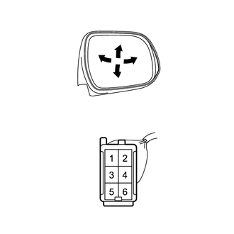
| *a | Component without harness connected
(Outer Rear View Mirror Assembly RH) |
Disconnect the mirror connector.
Apply battery voltage and check operation of the mirror.
- OK:
Measurement Condition Specified Condition Battery positive (+) →Terminal 5 (MV)
Battery negative (-) → Terminal 3 (M+)Turns upward Battery positive (+) → Terminal 3 (M+)
Battery negative (-) → Terminal 5 (MV)Turns downward Battery positive (+) → Terminal 1 (MH)
Battery negative (-) → Terminal 3 (M+)Turns left Battery positive (+) → Terminal 3 (M+)
Battery negative (-) → Terminal 1 (MH)Turns right
If the result is not as specified, replace the outer rear view mirror assembly RH.
w/ side turn signal light:
Check the side turn signal light.
Apply battery voltage to the terminals of the connector, and check the illumination condition.
- OK:
Tester Connection Specified Condition Battery positive (+) → Terminal 4 (B)
Battery negative (-) → Terminal 2 (E)Side turn light illuminates
If the result is not as specified, check the side turn signal light assembly RH (See pageVehicle Exterior>LIGHTING (EXT)>SIDE TURN SIGNAL LIGHT ASSEMBLY(for Outer Rear View Mirror)>INSPECTION).