Home › Vehicle Exterior › WINDOW / GLASS › POWER WINDOW CONTROL SYSTEM(w/ Jam Protection Function) › from 2013.08
RM1880E _59 Vehicle Exterior _013248 WINDOW / GLASS _0068699 POWER WINDOW CONTROL SYSTEM(w/ Jam Protection Function) J

WINDOW / GLASS  POWER WINDOW CONTROL SYSTEM(w/ Jam Protection Function)  Auto Up / Down Function does not Operate  


DESCRIPTION

If the auto up/down function does not operate, the cause may be one or more of the following:

·

The recorded power window fully closed position, which is stored in the power window regulator master switch assembly, was erased as a result of: 1) the PWR H-fuse or DOOR fuse being replaced; or 2) the battery cable and the master switch's connector being disconnected.

·

The power window regulator master switch assembly has a malfunction.

·

The pulse sensors in the front power window regulator motor assembly RH have a malfunction.

·

The wiring between the power window regulator master switch assembly and the front power window regulator motor assembly RH is open or short-circuited.


WIRING DIAGRAM
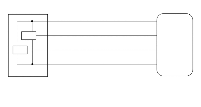
B276696
5.385,2.938 7.052,3.594 1.667,0.656 10 false Power Window Regulator Master Switch Assembly 0.271,2.979 2.271,3.635 2,0.656 10 false Front Power Window Regulator Motor Assembly RH 0.896,1.188 1.333,1.49 0.438,0.302 10 false PLS 5.646,0.667 6.094,0.969 0.448,0.302 10 false VCC 5.646,1.177 6.146,1.448 0.5,0.271 10 false PLS 5.646,1.688 6.198,2.031 0.552,0.344 10 false PLS2 5.646,2.208 6.104,2.5 0.458,0.292 10 false GND 0.583,1.698 1.125,2.031 0.542,0.333 10 false PLS 1.729,0.583 2.01,0.875 0.281,0.292 10 false 4 1.729,1.104 2.073,1.406 0.344,0.302 10 false 5 1.74,1.604 2.083,1.917 0.344,0.313 10 false 3 1.74,2.115 2.094,2.458 0.354,0.344 10 false 6 1.281,0.781 1.885,1.094 0.604,0.313 10 false SSRB 1.396,1.292 1.865,1.594 0.469,0.302 10 false PLS 1.313,1.802 1.917,2.115 0.604,0.313 10 false PLS2 1.573,2.302 1.938,2.604 0.365,0.302 10 false E 5.469,0.583 5.708,0.854 0.24,0.271 10 false 3 5.406,1.094 5.677,1.323 0.271,0.229 10 false 14 5.417,1.604 5.792,1.927 0.375,0.323 10 false 17 5.479,2.115 5.844,2.417 0.365,0.302 10 false 2 0.271,2.802 0.583,3.063 0.313,0.26 10 false H2 5.385,2.76 5.781,3.01 0.396,0.25 10 false H8

PROCEDURE

1.CHECK MANUAL UP/DOWN FUNCTION (FOR DRIVER SIDE)
a.

Check that the manual up/down function operates normally.

OK:

Manual up/down function operates normally.


Result:
Proceed to
OK
NG


OK

2.PERFORM INITIALIZATION

NG

2.PERFORM INITIALIZATION
a.

Initialize the front power window regulator motor assembly RH.

Click hereVehicle Exterior>WINDOW / GLASS>POWER WINDOW CONTROL SYSTEM(w/ Jam Protection Function)>INITIALIZATION


b.

Check that the driver side door power window moves when the auto up and down functions of the power window regulator master switch assembly are operated.

Click hereVehicle Exterior>WINDOW / GLASS>POWER WINDOW CONTROL SYSTEM(w/ Jam Protection Function)>OPERATION CHECK

OK:

Driver side auto up and down functions are normal.


Result:
Proceed to
OK
NG


OK

END (POWER WINDOW CONTROL SYSTEM HAS NOT BEEN INITIALIZED)

NG

3.CHECK HARNESS AND CONNECTOR (POWER WINDOW REGULATOR MASTER SWITCH ASSEMBLY - FRONT POWER WINDOW REGULATOR MOTOR ASSEMBLY RH)
a.

Disconnect the H8 power window regulator master switch assembly connector.


b.

Disconnect the H2 front power window regulator motor assembly RH connector.


c.

Measure the resistance according to the value(s) in the table below.

Standard Resistance:
Tester Connection Condition Specified Condition
H8-3 (VCC) - H2-4 (SSRB) Always Below 1 Ω
H8-14 (PLS) - H2-5 (PLS) Always Below 1 Ω
H8-17 (PLS2) - H2-3 (PLS2) Always Below 1 Ω
H8-2 (GND) - H2-6 (E) Always Below 1 Ω
H8-3 (VCC) or H2-4 (SSRB) - Body ground Always 10 kΩ or higher
H8-14 (PLS) or H2-5 (PLS) - Body ground Always 10 kΩ or higher
H8-17 (PLS2) or H2-3 (PLS2) - Body ground Always 10 kΩ or higher


Result:
Proceed to
OK
NG


OK

4.CHECK POWER WINDOW REGULATOR MASTER SWITCH ASSEMBLY (PLS, PLS2 SIGNAL)

NG

REPAIR OR REPLACE HARNESS OR CONNECTOR

4.CHECK POWER WINDOW REGULATOR MASTER SWITCH ASSEMBLY (PLS, PLS2 SIGNAL)
a.

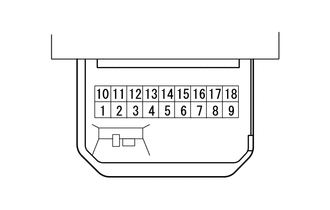
Remove the power window regulator master switch assembly with its connectors still connected.

Click hereVehicle Exterior>WINDOW / GLASS>POWER WINDOW MASTER SWITCH>REMOVAL

b.
B276285
0.208,0.927 0.625,1.177 0.417,0.25 1.729,0.938 1.5,0.448 true 2.25,0.948 2.396,0.458 true 0.177,0.156 0.49,0.417 0.313,0.26 10 false *a 0.333,0.979 0.813,1.313 0.479,0.333 10 false H8 1.313,0.25 1.792,0.583 0.479,0.333 10 false PLS 2.323,0.26 2.802,0.594 0.479,0.333 10 false PLS2
*a Component with harness connected
(Power Window Regulator Master Switch Assembly)


Using an oscilloscope, check the waveform.

OK:
Tester Connection Switch Condition Specified Condition
H8-14 (PLS) - Body ground Ignition switch ON, driver side power window switch off → up or down Pulse waveform is output
H8-17 (PLS2) - Body ground


Result:
Proceed to
OK
NG


OK

REPLACE POWER WINDOW REGULATOR MASTER SWITCH ASSEMBLY

NG

REPLACE FRONT POWER WINDOW REGULATOR MOTOR ASSEMBLY RH