12 Crankshaft Position Sensor Circuit Malfunction
Diagnostic trouble codes · Vehicles built Aug 2013 – Jul 2014
Versions by build date: Aug 2013 – Jul 2014 from Aug 2014
DESCRIPTION
The crankshaft position sensor in the engine control system contains a signal plate and a pickup coil for the TDC signal. The TDC signal plate has 1 tooth on its outer circumference. The TDC signal sensor generates 1 signal for every crankshaft revolution. The ECM detects the top dead center position based on the TDC signal.| DTC Code |
DTC Detection Condition |
Trouble Area |
| 12 |
No TDC signal is sent to the ECM at 400 rpm or more. |
|
WIRING DIAGRAM
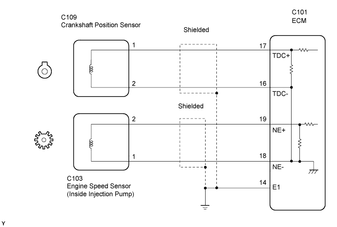

INSPECTION PROCEDURE
| 1. INSPECT CRANKSHAFT POSITION SENSOR |

Inspect the crankshaft position sensor (Click here).
|
|
||||

| OK | |
 |
| 2. CHECK ECM (TDC, NE SIGNAL) |
While cranking or idling, check the waveforms according to the value(s) in the table below.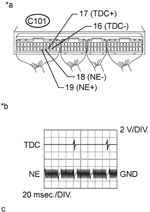
- OK:
Tester Connection
Condition
Specified Condition
C101-17 (TDC+) - C101-16 (TDC-)
Idling
Correct waveform is as shown
C101-19 (NE+) - C101-18 (NE-)
Idling
Correct waveform is as shown
Text in Illustration *a
Component with harness connected
(ECM)
*b
TDC and NE Signal Waveforms
|
|
||||

| OK | ||
 |
||
| ||
| 3. CHECK HARNESS AND CONNECTOR (ECM - CRANKSHAFT POSITION SENSOR) |
Disconnect the crankshaft position sensor connector.
Disconnect the ECM connector.
Measure the resistance according to the value(s) in the table below.
- Standard Resistance (Check for Open):
Tester Connection
Condition
Specified Condition
C109-1 - C101-17 (TDC+)
Always
Below 1 Ω
C109-2 - C101-16 (TDC-)
Always
Below 1 Ω
- Standard Resistance (Check for Short):
Tester Connection
Condition
Specified Condition
C109-1 or C101-17 (TDC+) - Body ground
Always
10 kΩ or higher
C109-2 or C101-16 (TDC-) - Body ground
Always
10 kΩ or higher
Reconnect the crankshaft position sensor connector.
Reconnect the ECM connector.
|
|
||||
| OK | ||
|
||
| ||