Door Courtesy Switch Circuit
Circuit diagnosis · Vehicles built Aug 2013 – Jul 2014
Versions by build date: Aug 2013 – Jul 2014 from Aug 2014
DESCRIPTION
The main body ECU receives a door open/closed signal from each door courtesy light switch.WIRING DIAGRAM
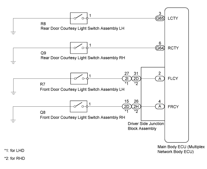

INSPECTION PROCEDURE
| 1. READ VALUE USING INTELLIGENT TESTER (DOOR COURTESY LIGHT SWITCH) |

Using the intelligent tester, read the Data List (Click here).
Main Body Tester Display
Measurement Item/Range
Normal Condition
Diagnostic Note
RR Door Courtesy SW*
Rear door courtesy light switch RH signal / ON or OFF
ON: Rear door RH open
OFF: Rear door RH closed
-
RL Door Courtesy SW*
Rear door courtesy light switch LH signal / ON or OFF
ON: Rear door LH open
OFF: Rear door LH closed
-
FR Door Courtesy
Front door courtesy light switch RH signal / ON or OFF
ON: Front door RH open
OFF: Front door RH closed
-
FL Door Courtesy
Front door courtesy light switch LH signal / ON or OFF
ON: Front door LH open
OFF: Front door LH closed
-
- *: for 5 Door
- OK:
- The display is as specified in the normal condition column.
Result Result
Proceed to
OK
A
NG (Front door courtesy light switch does not operate)
B
NG (Rear door courtesy light switch does not operate)
C
- *: for 5 Door
|
|
||||
|
|
||||

| A | ||
 |
||
| ||
| 2. INSPECT FRONT DOOR COURTESY LIGHT SWITCH ASSEMBLY |
Remove the front door courtesy light switch (Click here).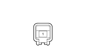
Measure the resistance according to the value(s) in the table below.
- Standard Resistance:
Tester Connection
Switch Condition
Specified Condition
1 - Switch body
Pin not pushed
Below 1 Ω
Pin pushed
10 kΩ or higher
|
|
||||

| OK | |
 |
| 3. CHECK HARNESS AND CONNECTOR (MAIN BODY ECU - FRONT DOOR COURTESY LIGHT SWITCH ASSEMBLY) |
Remove the main body ECU (Click here).
Disconnect the R7 or Q8 front door courtesy light switch connector.
Measure the resistance according to the value(s) in the table below.
- Standard Resistance:
- for LH:
Tester Connection
Condition
Specified Condition
A-2 (FLCY) - R7-1
Always
Below 1 Ω
A-2 (FLCY) - Body ground
Always
10 kΩ or higher
- for RH:
Tester Connection
Condition
Specified Condition
A-4 (FRCY) - Q8-1
Always
Below 1 Ω
A-4 (FRCY) - Body ground
Always
10 kΩ or higher
|
|
||||
| OK | |
|
| 4. CHECK DRIVER SIDE JUNCTION BLOCK ASSEMBLY |
for LHD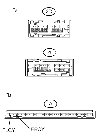
Disconnect the 2D or 2I driver side junction block connector.
Remove the main body ECU (Click here).
Measure the resistance according to the value(s) in the table.
- Standard Resistance:
- for LH:
Tester Connection
Condition
Specified Condition
A-2 (FLCY) - 2I-27
Always
Below 1 Ω
A-2 (FLCY) - Body ground
Always
10 kΩ or higher
- for RH:
Tester Connection
Condition
Specified Condition
A-4 (FRCY) - 2D-15
Always
Below 1 Ω
A-4 (FRCY) - Body ground
Always
10 kΩ or higher
| *a |
Front view of wire harness connector (to Driver Side Junction Block Assembly) |
| *b |
Front view of wire harness connector (to Main Body ECU) |
for RHD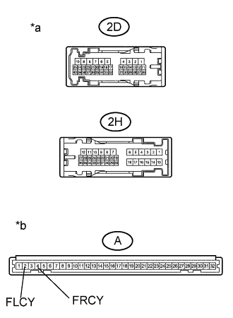
Disconnect the 2D or 2H driver side junction block connector.
Remove the main body ECU (Click here).
Measure the resistance according to the value(s) in the table.
- Standard Resistance:
- for LH:
Tester Connection
Condition
Specified Condition
A-2 (FLCY) - 2D-31
Always
Below 1 Ω
A-2 (FLCY) - Body ground
Always
10 kΩ or higher
- for RH:
Tester Connection
Condition
Specified Condition
A-4 (FRCY) - 2H-26
Always
Below 1 Ω
A-4 (FRCY) - Body ground
Always
10 kΩ or higher
| *a |
Front view of wire harness connector (to Driver Side Junction Block Assembly) |
| *b |
Front view of wire harness connector (to Main Body ECU) |
|
|
||||
| OK | ||
|
||
| ||
| 5. INSPECT REAR DOOR COURTESY LIGHT SWITCH ASSEMBLY |
Remove the rear door courtesy light switch (Click here).
Measure the resistance according to the value(s) in the table below.
- Standard Resistance:
Tester Connection
Switch Condition
Specified Condition
1 - Switch body
Pin not pushed
Below 1 Ω
Pin pushed
10 kΩ or higher
|
|
||||
| OK | |
|
| 6. CHECK HARNESS AND CONNECTOR (MAIN BODY ECU - REAR DOOR COURTESY LIGHT SWITCH ASSEMBLY) |
Disconnect the G64 or G65 main body ECU connector.
Disconnect the R8 or Q9 rear door courtesy light switch connector.
Measure the resistance according to the value(s) in the table below.
- Standard Resistance:
- for LH:
Tester Connection
Condition
Specified Condition
G65-3 (LCTY) - R8-1
Always
Below 1 Ω
G65-3 (LCTY) - Body ground
Always
10 kΩ or higher
- for RH:
Tester Connection
Condition
Specified Condition
G64-6 (RCTY) - Q9-1
Always
Below 1 Ω
G64-6 (RCTY) - Body ground
Always
10 kΩ or higher
|
|
||||
| OK | ||
|
||
| ||