INSPECTION
Inspection · Vehicles built from Aug 2013
| INSPECT COUNTER GEAR |

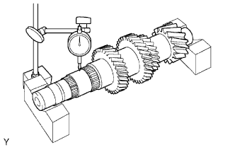  |
Using a dial indicator and 2 V-blocks, measure the shaft runout.
- Maximum runout:
- 0.03 mm (0.00118 in.)
Using a micrometer, measure the journal diameter of each input shaft journal, at the specified positions.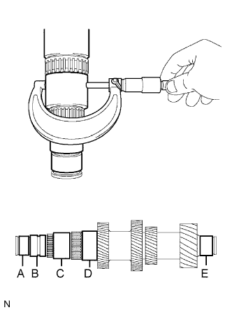
- Standard Journal Diameter:
Item
Specified Condition
Journal A
34.002 to 34.015 mm (1.3387 to 1.3392 in.)
Journal B
36.985 to 37.000 mm (1.4561 to 1.4567 in.)
Journal C
47.985 to 48.000 mm (1.8892 to 1.8898 in.)
Journal D
53.985 to 54.000 mm (2.1254 to 2.1260 in.)
Journal E
34.002 to 34.015 mm (1.3387 to 1.3392 in.)
- Minimum Journal Diameter:
Item
Specified Condition
Journal A
34.002 mm (1.3387 in.)
Journal B
36.985 mm (1.4561 in.)
Journal C
47.985 mm (1.8892 in.)
Journal D
53.985 mm (2.1254 in.)
Journal E
34.002 mm (1.3387 in.)
| INSPECT COUNTER SHAFT REVERSE GEAR |
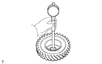 |
Using a cylinder gauge, measure the inside diameter of the reverse gear.
- Standard inside diameter:
- 51.015 to 51.040 mm (2.0085 to 2.0095 in.)
- Maximum inside diameter:
- 51.040 mm (2.0095 in.)
| INSPECT COUNTER SHAFT 1ST SPEED GEAR |
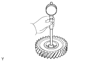 |
Using a cylinder gauge, measure the inside diameter of the 1st gear.
- Standard inside diameter:
- 54.015 to 54.040 mm (2.1266 to 2.1276 in.)
- Maximum inside diameter:
- 54.040 mm (2.1276 in.)
| INSPECT COUNTER SHAFT 2ND SPEED GEAR |
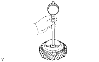 |
Using a cylinder gauge, measure the inside diameter of the 2nd gear.
- Standard inside diameter:
- 60.015 to 60.040 mm (2.3628 to 2.3638 in.)
- Maximum inside diameter:
- 60.040 mm (2.3638 in.)
| INSPECT NO. 3 TRANSMISSION HUB SLEEVE |
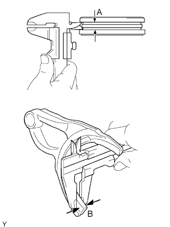 |
Using a vernier caliper, measure the width of the No. 3 transmission hub sleeve groove (A) and the thickness of the claw part of the gear shift fork No. 4 (B), and calculate the clearance.
- Standard clearance (A - B):
- 0.26 to 0.84 mm (0.0102 to 0.0331 in.)
| INSPECT NO. 1 TRANSMISSION HUB SLEEVE |
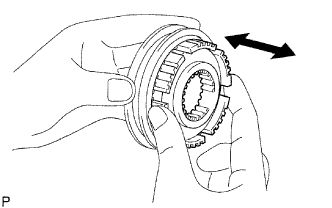 |
Check the sliding condition between the No. 1 transmission hub and No. 1 transmission hub sleeve.
Check that the splines of the No. 1 transmission hub sleeve are not worn.
Using a vernier caliper, measure the width of the No. 1 transmission hub sleeve groove (A) and the thickness of the claw part of the No. 1 gear shift fork (B), and calculate the clearance.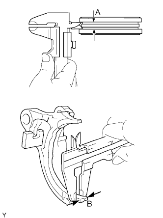
- Standard clearance (A - B):
- 0.15 to 0.35 mm (0.00591 to 0.0138 in.)
| INSPECT NO. 4 SYNCHRONIZER RING |
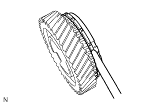 |
Using a feeler gauge, measure the clearance between the synchronizer ring and reverse gear.
- Standard clearance:
- 0.70 to 1.50 mm (0.0276 to 0.0590 in.)
- Minimum clearance:
- 0.70 mm (0.0276 in.)
Coat the reverse gear cone with gear oil.
Check the braking effect of the synchronizer ring.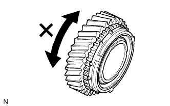
Turn the synchronizer ring in both directions while pushing it against the reverse gear cone. Check that the ring locks in both directions.
- If No. 4 synchronizer ring turns, replace it.
- If No. 4 synchronizer ring turns, replace it.
| INSPECT NO. 1 SYNCHRONIZER RING SET (for 1st Gear) |
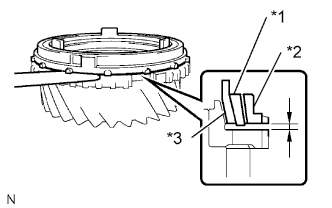 |
Using a feeler gauge, measure the clearance between the synchronizer ring and 1st gear.
- Standard clearance:
- Inner:
- 1.48 to 2.12 mm (0.0583 to 0.0835 in.)
- Middle:
- 0.68 to 1.92 mm (0.0268 to 0.0756 in.)
- Outer:
- 0.88 to 1.72 mm (0.0346 to 0.0677 in.)
- Minimum clearance:
- Inner:
- 1.48 mm (0.0583 in.)
- Middle:
- 0.68 mm (0.0268 in.)
- Outer:
- 0.88 mm (0.0346 in.)
If the clearance is less than the minimum, replace the synchronizer ring.Text in Illustration *1
Middle
*2
Outer
*3
Inner
Coat the 1st gear cone with gear oil.
Check the braking effect of the synchronizer ring.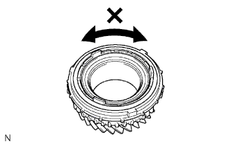
Turn the synchronizer ring in both directions while pushing it against the 1st gear cone. Check that the ring locks in both directions.
- If No. 1 synchronizer ring set turns, replace it.
- If No. 1 synchronizer ring set turns, replace it.
| INSPECT NO. 1 SYNCHRONIZER RING SET (for 2nd Gear) |
|
|
Using a feeler gauge, measure the clearance between the synchronizer ring and 2nd gear.
- Standard clearance:
- Inner:
- 1.48 to 2.12 mm (0.0583 to 0.0835 in.)
- Middle:
- 0.68 to 1.92 mm (0.0268 to 0.0756 in.)
- Outer:
- 0.88 to 1.72 mm (0.0346 to 0.0677 in.)
- Minimum clearance:
- Inner:
- 1.48 mm (0.0583 in.)
- Middle:
- 0.68 mm (0.0268 in.)
- Outer:
- 0.88 mm (0.0346 in.)
If the clearance is less than the minimum, replace the synchronizer ring.Text in Illustration *1
Middle
*2
Outer
*3
Inner
Coat the 2nd gear cone with gear oil.
Check the braking effect of the synchronizer ring.
Turn the synchronizer ring in both directions while pushing it against the 2nd gear cone. Check that the ring locks in both directions.
- If No. 1 synchronizer ring set turns, replace it.
- If No. 1 synchronizer ring set turns, replace it.