REASSEMBLY
Removal / installation · Vehicles built from Aug 2013
| 1. INSTALL COUNTER GEAR REAR RADIAL BALL BEARING |

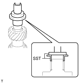  |
Using SST and a press, install a new radial ball bearing (inner race) to the counter gear.
- SST
- 09316-60011
(09316-00041)
09950-60010 (09951-00540)
| 2. INSTALL COUNTER GEAR REAR BEARING SNAP RING |
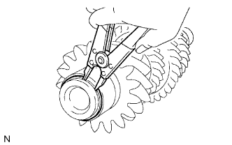 |
Select a new snap ring that will allow minimal axial play.
- Standard clearance:
- 0.1 mm (0.00394 in.) or less
- Standard Snap Ring:
Part No.
Mark
Thickness
90520-31015
A
2.35 to 2.40 mm
(0.0925 to 0.0945 in.)
90520-31016
B
2.40 to 2.45 mm
(0.0945 to 0.0965 in.)
90520-31017
C
2.45 to 2.50 mm
(0.0965 to 0.0984 in.)
90520-31018
D
2.50 to 2.55 mm
(0.0984 to 0.1004 in.)
90520-31019
E
2.55 to 2.60 mm
(0.1004 to 0.1024 in.)
90520-31020
F
2.60 to 2.65 mm
(0.1024 to 0.1043 in.)
90520-31021
G
2.65 to 2.70 mm
(0.1043 to 0.1063 in.)
90520-31022
H
2.70 to 2.75 mm
(0.1063 to 0.1083 in.)
90520-31023
J
2.75 to 2.80 mm
(0.1083 to 0.1102 in.)
90520-31024
K
2.80 to 2.85 mm
(0.1102 to 0.1122 in.)
90520-31025
L
2.85 to 2.90 mm
(0.1122 to 0.1142 in.)
90520-31033
M
2.90 to 2.95 mm
(0.1142 to 0.1161 in.)
Using a snap ring expander, install the snap ring to the counter gear.
| 3. INSTALL NO. 1 TRANSMISSION CLUTCH HUB |
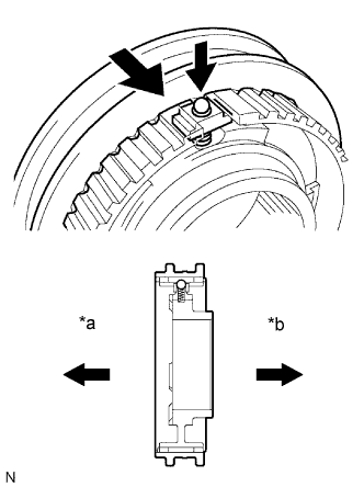 |
Apply a light coat of gear oil to the sleeve and hub.
Install the clutch hub to the clutch hub sleeve.
Text in Illustration *a
1st Gear Side
*b
2nd Gear Side
Install one of the balls to each shifting key.
Install one of the springs to each shifting key.
Install the shifting keys with balls and springs to the No. 1 clutch hub.
- NOTICE:
- Be careful to prevent the balls from flying off.
| 4. INSTALL 2ND GEAR NEEDLE ROLLER BEARING |
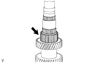 |
Coat the 2nd gear needle roller bearing with gear oil, and then install it to the counter gear.
| 5. INSTALL COUNTER SHAFT 2ND SPEED GEAR |
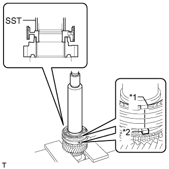 |
Coat the counter shaft 2nd speed gear with gear oil, and then install it to the counter gear.
Coat the No. 1 synchronizer ring set with gear oil, and then install it to the counter gear.
Using SST and a press, install the No. 1 transmission clutch hub to the counter gear.
- SST
- 09316-60011
Text in Illustration *a
Groove
*b
Protrusion
- HINT:
- Align the groove of the clutch hub with the protrusion of the synchronizer ring.
Check that the gear and synchronizer ring move smoothly.
| 6. INSTALL NO. 1 CLUTCH HUB SHAFT SNAP RING |
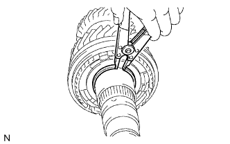 |
Select a new snap ring that will allow minimal axial play.
- Standard clearance:
- 0.1 mm (0.00394 in.) or less
- Standard Snap Ring:
Part No.
Mark
Thickness
90520-45013
A
2.28 to 2.33 mm
(0.0898 to 0.0917 in.)
90520-45014
B
2.33 to 2.38 mm
(0.0917 to 0.0937 in.)
90520-45015
C
2.38 to 2.43 mm
(0.0937 to 0.0957 in.)
90520-45016
D
2.43 to 2.48 mm
(0.0957 to 0.0976 in.)
90520-45017
E
2.48 to 2.53 mm
(0.0976 to 0.0996 in.)
90520-45018
F
2.53 to 2.58 mm
(0.0996 to 0.1016 in.)
90520-45019
G
2.58 to 2.63 mm
(0.1016 to 0.1035 in.)
Using a snap ring expander, install the snap ring to the counter gear.
| 7. INSTALL NO. 1 SYNCHRONIZER RING SET (for 1st Gear) |
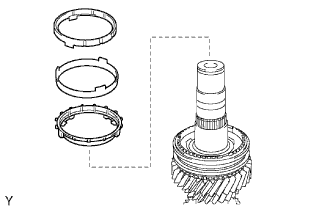 |
Coat the No. 1 synchronizer ring set with gear oil, and then install it to the counter gear.
| 8. INSTALL 1ST GEAR NEEDLE ROLLER BEARING |
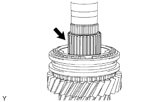 |
Coat the 1st gear needle roller bearing with gear oil, and then install it to the counter gear.
| 9. INSTALL COUNTER SHAFT 1ST SPEED GEAR |
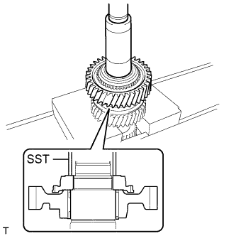 |
Coat the counter shaft 1st speed gear with gear oil and install it to the counter gear.
Using SST and a press, install the reverse gear spline piece.
- SST
- 09309-37010
| 10. INSTALL BALL |
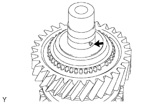 |
Install the ball to the counter gear.
| 11. INSTALL NO. 4 SYNCHRONIZER RING |
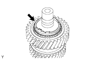 |
Coat the No. 4 synchronizer ring with gear oil and install it to the counter gear.
| 12. INSTALL REVERSE GEAR NEEDLE ROLLER BEARING |
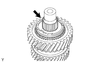 |
Coat the reverse gear needle roller bearing with gear oil and install it to the counter gear.
| 13. INSTALL COUNTERSHAFT REVERSE GEAR |
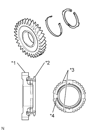 |
Install the key spring and 2 shifting keys to the reverse gear.
Text in Illustration *1
Reverse Gear
*2
Hub Sleeve
*3
Shifting Key
*4
Key Spring
- HINT:
- Install each shifting key with its groove on the reverse gear side.
- Install the key spring with its claw on the reverse gear side.
- Refer to the illustration when installing the key spring.
- Install each shifting key with its groove on the reverse gear side.
Install the hub sleeve to the reverse gear.
Coat the countershaft reverse gear with gear oil, and then install it to the counter gear.
| 14. INSTALL REVERSE GEAR BEARING RACE INNER |
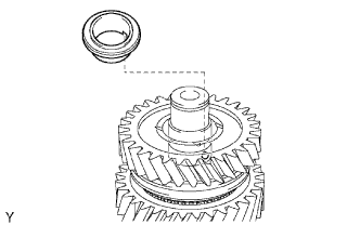 |
Align the groove of the reverse gear bearing race inner with the ball and install the reverse gear bearing race inner.
| 15. INSTALL COUNTER GEAR FRONT BEARING |
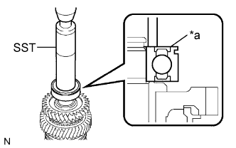 |
Using SST and a press, install the counter gear front bearing or roller to the counter gear.
- SST
- 09608-06041
Text in Illustration *a
Groove
- HINT:
- Make sure that the groove of the bearing faces the correct direction as shown in the illustration.
| 16. INSTALL NO. 1 COUNTER GEAR FRONT BEARING SNAP RING |
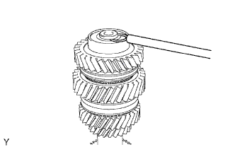 |
Select a new snap ring that will allow minimal axial play.
- Standard clearance:
- 0.1 mm (0.00394 in.) or less
- Standard Snap Ring:
Part No.
Mark
Thickness
90520-31015
A
2.35 to 2.40 mm
(0.0925 to 0.0945 in.)
90520-31016
B
2.40 to 2.45 mm
(0.0945 to 0.0965 in.)
90520-31017
C
2.45 to 2.50 mm
(0.0965 to 0.0984 in.)
90520-31018
D
2.50 to 2.55 mm
(0.0984 to 0.1004 in.)
90520-31019
E
2.55 to 2.60 mm
(0.1004 to 0.1024 in.)
90520-31020
F
2.60 to 2.65 mm
(0.1024 to 0.1043 in.)
90520-31021
G
2.65 to 2.70 mm
(0.1043 to 0.1063 in.)
90520-31022
H
2.70 to 2.75 mm
(0.1063 to 0.1083 in.)
90520-31023
J
2.75 to 2.80 mm
(0.1083 to 0.1102 in.)
90520-31024
K
2.80 to 2.85 mm
(0.1102 to 0.1122 in.)
90520-31025
L
2.85 to 2.90 mm
(0.1122 to 0.1142 in.)
0520-31033
M
2.90 to 2.95 mm
(0.1142 to 0.1161 in.)
Using a snap ring expander, install the snap ring to the counter gear.
| 17. INSPECT REVERSE GEAR THRUST CLEARANCE |
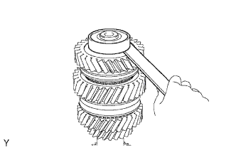 |
Using a feeler gauge, measure the reverse gear thrust clearance.
- Standard clearance:
- 0.125 to 0.375 mm (0.00493 to 0.0148 in.)
- HINT:
- Replace the part or parts determined to be the most likely cause of the problem.
| 18. INSPECT 1ST GEAR THRUST CLEARANCE |
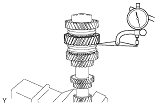 |
Using a dial indicator, measure the 1st gear thrust clearance.
- Standard clearance:
- 0.10 to 0.43 mm (0.00394 to 0.0169 in.)
- HINT:
- Replace the part or parts determined to be the most likely cause of the problem.
| 19. INSPECT 2ND GEAR THRUST CLEARANCE |
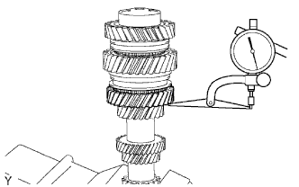 |
Using a dial indicator, measure the 2nd gear thrust clearance.
- Standard clearance:
- 0.10 to 0.43 mm (0.00394 to 0.0169 in.)
- HINT:
- Replace the part or parts determined to be the most likely cause of the problem.
| 20. INSPECT REVERSE GEAR RADIAL CLEARANCE |
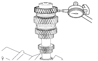 |
Using a dial indicator, measure the reverse gear radial clearance.
- Standard clearance:
- 0.015 to 0.065 mm (0.000591 to 0.00255 in.)
- HINT:
- Replace the part or parts determined to be the most likely cause of the problem.
| 21. INSPECT 1ST GEAR RADIAL CLEARANCE |
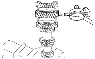 |
Using a dial indicator, measure the 1st gear radial clearance.
- Standard clearance:
- 0.015 to 0.067 mm (0.000591 to 0.00263 in.)
- HINT:
- Replace the part or parts determined to be the most likely cause of the problem.
| 22. INSPECT 2ND GEAR RADIAL CLEARANCE |
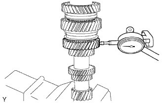 |
Using a dial indicator, measure the 2nd gear radial clearance.
- Standard clearance:
- 0.015 to 0.067 mm (0.000591 to 0.00263 in.)