INSTALLATION
Removal / installation · Vehicles built from Aug 2013
| 1. INSTALL CRANKSHAFT POSITION SENSOR |

Apply a light coat of engine oil to the O-ring of the crankshaft position sensor.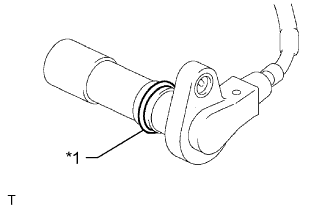

Text in Illustration *1
O-Ring
Install the crankshaft position sensor with the bolt.
- Torque:
- 8.5 N*m{ 87 kgf*cm , 75 in.*lbf }
- NOTICE:
- Make sure that the O-ring is not cracked or jammed when installing.
Connect the crankshaft position sensor connector and attach the wire harness clamp.
| 2. INSTALL NO. 1 COMPRESSOR MOUNTING BRACKET |
- NOTICE:
- Install the No. 1 compressor mounting bracket exactly as described in the procedures below to properly secure and prevent damage to the fan and generator V belt.
Temporarily install the No. 1 compressor mounting bracket with the 3 bolts.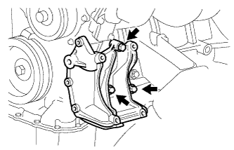
- HINT:
- Temporarily install the No. 1 compressor mounting bracket with the 3 bolts so that the bracket can be moved by hand.
Push the No. 1 compressor mounting bracket toward the cylinder block as shown in the illustration and tighten bolt B.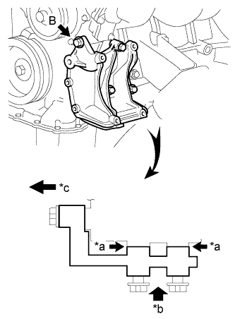
- Torque:
- for bolt B:
- 45 N*m{ 459 kgf*cm , 33 ft.*lbf }
Text in Illustration *a
No Clearance
*b
Push
*c
Front
- HINT:
- Make sure there is no clearance between the cylinder block and No. 1 compressor mounting bracket as shown in the illustration.
Uniform tighten the 4 bolts in the order shown in the illustration.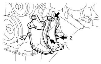
- Torque:
- for bolt A:
- 45 N*m{ 459 kgf*cm , 33 ft.*lbf }
- for bolt C:
- 25 N*m{ 250 kgf*cm , 18 ft.*lbf }
Text in Illustration 
Bolt A

Bolt C
| 3. CONNECT COOLER COMPRESSOR ASSEMBLY |
Temporarily install the cooler compressor with the 4 bolts.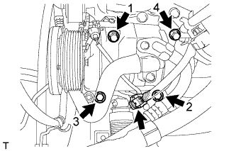
Tighten the bolts in the order shown in the illustration to connect the cooler compressor.
- Torque:
- 25 N*m{ 250 kgf*cm , 18 ft.*lbf }
Connect the connector.
Install the suction hose with the bolt.
- Torque:
- 7.8 N*m{ 80 kgf*cm , 69 in.*lbf }
| 4. CONNECT VANE PUMP ASSEMBLY |
Connect the vane pump with the 2 bolts.
- Torque:
- 21 N*m{ 214 kgf*cm , 15 ft.*lbf }
Connect the 2 connectors.
Install the pressure feed tube with the bolt.
- Torque:
- 28 N*m{ 285 kgf*cm , 21 ft.*lbf }
| 5. INSTALL FAN SHROUD |
Install the fan shroud (Click here).